
Environmental monitor device with database

a monitor device and database technology, applied in lighting and heating apparatus, heating types, instruments, etc., can solve the problems of poor air quality, unnecessary infections, and unnecessary imperfections in manufactured products

Active Publication Date: 2017-08-08
OBERON
View PDF11 Cites 22 Cited by
  • Summary
  • Abstract
  • Description
  • Claims
  • Application Information

AI Technical Summary

Benefits of technology

The present invention relates to an environmental sensor device that measures and reports air quality. The device includes a data bus, sensors, a processing unit, and a communications interface. It can be used in various settings such as healthcare facilities, semiconductor manufacturing facilities, and housing and office environments. The device can also be connected to external environmental monitoring devices and can be controlled through various factors such as air flow, temperature, particulate counts, and humidity. The invention provides a way to manage air quality to promote health and prevent contamination.

Problems solved by technology

For example, poor air quality in a health care facility such as a hospital may lead to unnecessary infections.
Poor air quality in a semiconductor manufacturing facility may lead to unnecessary imperfections in manufactured products.
Poor air quality in a housing and / or office environment may lead to long term exposure to harmful elements that may lead to cancer or other disorders.

Method used


Image

  • Environmental monitor device with database
  • Environmental monitor device with database
  • Environmental monitor device with database

Examples


Embodiment Construction

[0012]Some of the various embodiments of the present invention measure and report environmental air quality.

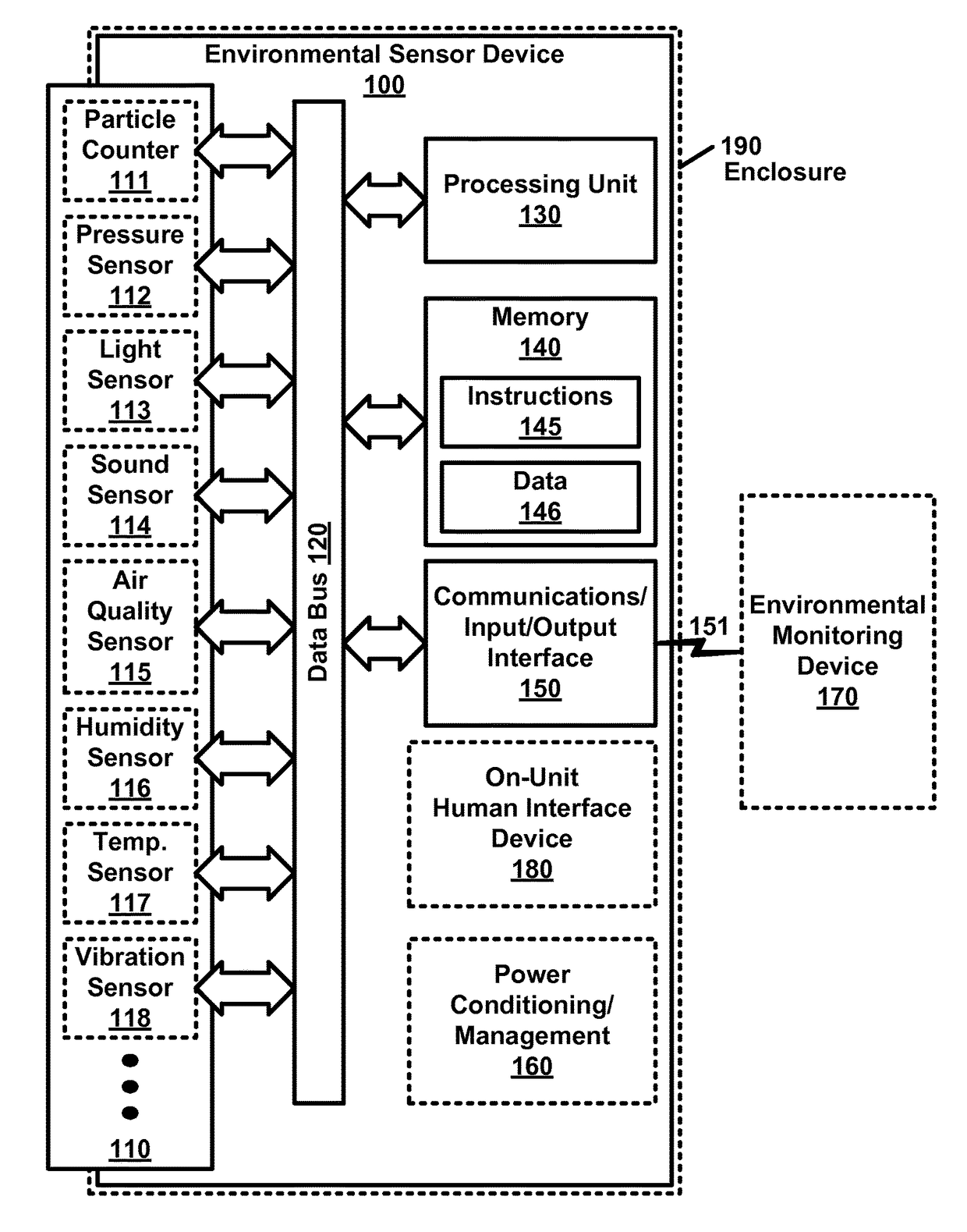
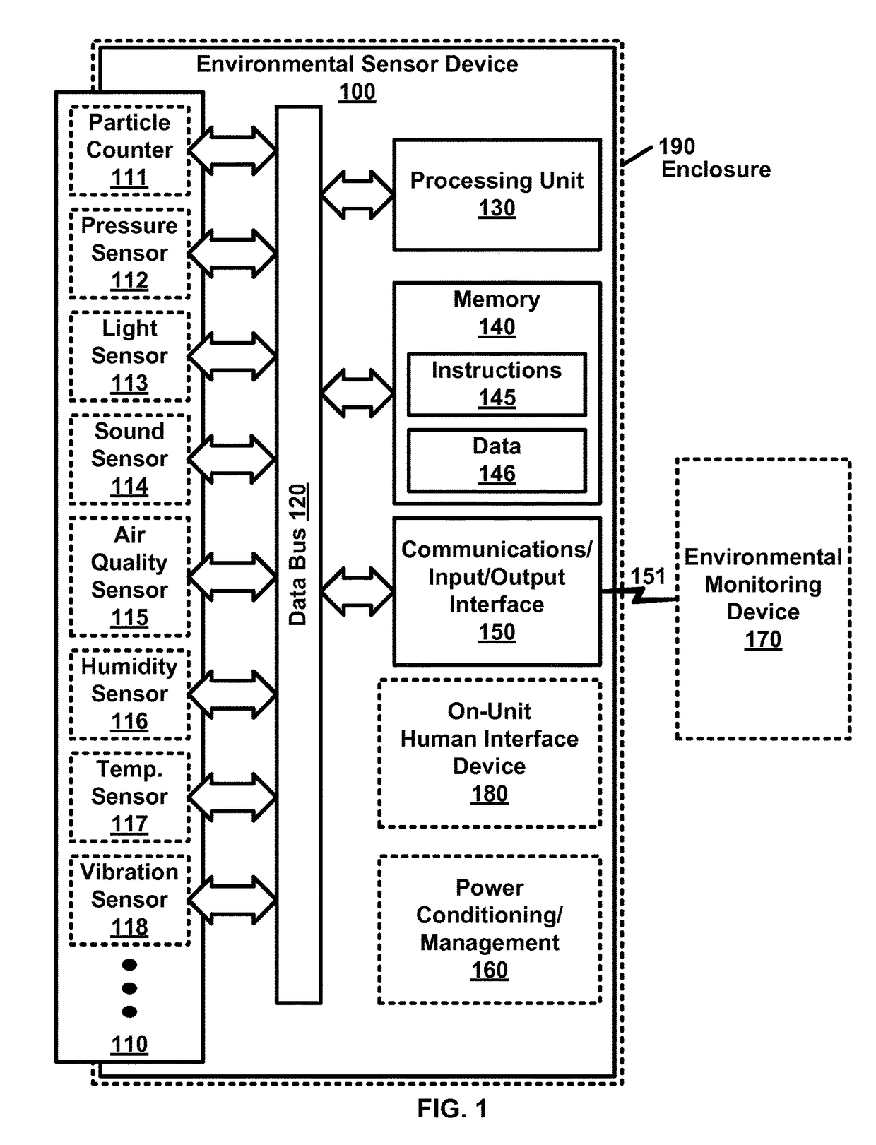
[0013]Example FIG. 1 is a block diagram illustrating an environmental sensor device 100 as per an aspect of an embodiment of the present invention. Embodiments of the environmental sensor device 100 may comprise a data bus 120, a multitude of sensors 110, at least one processing unit 130, at least one communications interface 150, and memory 140.

[0014]A data bus 120 is a communication system that transfers data between components inside or between electronic device(s). According to some of the embodiments, data bus 120 may include various hardware components (wire, optical fiber, etc.) and associated software, including communication protocols. Data buses may include parallel electrical wires with multiple connections. Data bus 120 may include a physical arrangement of electronic components and connections to provide the logical functionality of a parallel electrical bus. Some...


PUM

PropertyMeasurementUnit
wavelengthaaaaaaaaaa
resistanceaaaaaaaaaa

Abstract

An environmental monitor device with a database comprises a data bus, a multitude of sensors, at least one processing unit, input / output device(s); communications interface(s), and memory. Communications interface(s) communicate with at least one environmental sensor device comprising with a multitude of sensors. The multitude of sensors may include particle counter(s), pressure sensor(s) and / or the like. The memory is configured to hold data and machine executable instructions. The machine executable instructions are configured to cause at least one processing unit to: collect sensor data from at least one environmental sensor device; store at least some of the sensor data in at least one database; and generate a report of sensor data that exceeds at least one threshold.

Description

BACKGROUND[0001]Air quality may be affected by a wide range of factors including temperature, humidity, air-flow, occupancy, particulate counts, the presence of various chemical and biologic materials, and / or the like. Certain types of locations may need to maintain a standard of air quality. For example, poor air quality in a health care facility such as a hospital may lead to unnecessary infections. Poor air quality in a semiconductor manufacturing facility may lead to unnecessary imperfections in manufactured products. Poor air quality in a housing and / or office environment may lead to long term exposure to harmful elements that may lead to cancer or other disorders. Air quality may be managed using controlling factors such as, for example, air flow, temperature, particulate counts, and humidity.BRIEF DESCRIPTION OF THE SEVERAL VIEWS OF THE DRAWINGS[0002]Example FIG. 1 is a block diagram illustrating an environmental sensor device as per an aspect of an embodiment of the present ...

Claims


Application Information

Patent Timeline
Patent Type & Authority Patents(United States)
IPC IPC(8): G08C19/22G01N1/26G06F19/00H04Q9/00F24F11/00G16Z99/00
CPCH04Q9/00F24F11/00F24F11/001F24F11/0012F24F11/0015F24F11/0017G01N1/26G06F19/327F24F2011/005F24F2011/0023F24F2011/0053F24F2130/40F24F2130/30F24F2110/20F24F2110/50F24F11/30G16H40/20F24F2110/10F24F2110/00F24F2110/64Y02B30/70G16Z99/00F24F11/64F24F11/523F24F11/56
Inventor SCHULTZ, RICHARD DOUGLASDEGROOTE, DAVID GLENNWEAVER, TRAVIS JAMESTHOMPSON, SCOTT
Owner OBERON
Learn More