
Lifeguard positioning system and method

a positioning system and lifeguard technology, applied in the field of lifeguard line of sight testing methods, can solve the problems of difficulty in identifying visually a motionless body, difficulty in monitoring type, risk of drowning in a swimming pool, etc., to minimize drowning incidents, prevent drowning incidents, and minimize the risk of bather drowning

Active Publication Date: 2017-08-08
ROBSON FORENSIC
View PDF14 Cites 6 Cited by
  • Summary
  • Abstract
  • Description
  • Claims
  • Application Information

AI Technical Summary

Benefits of technology

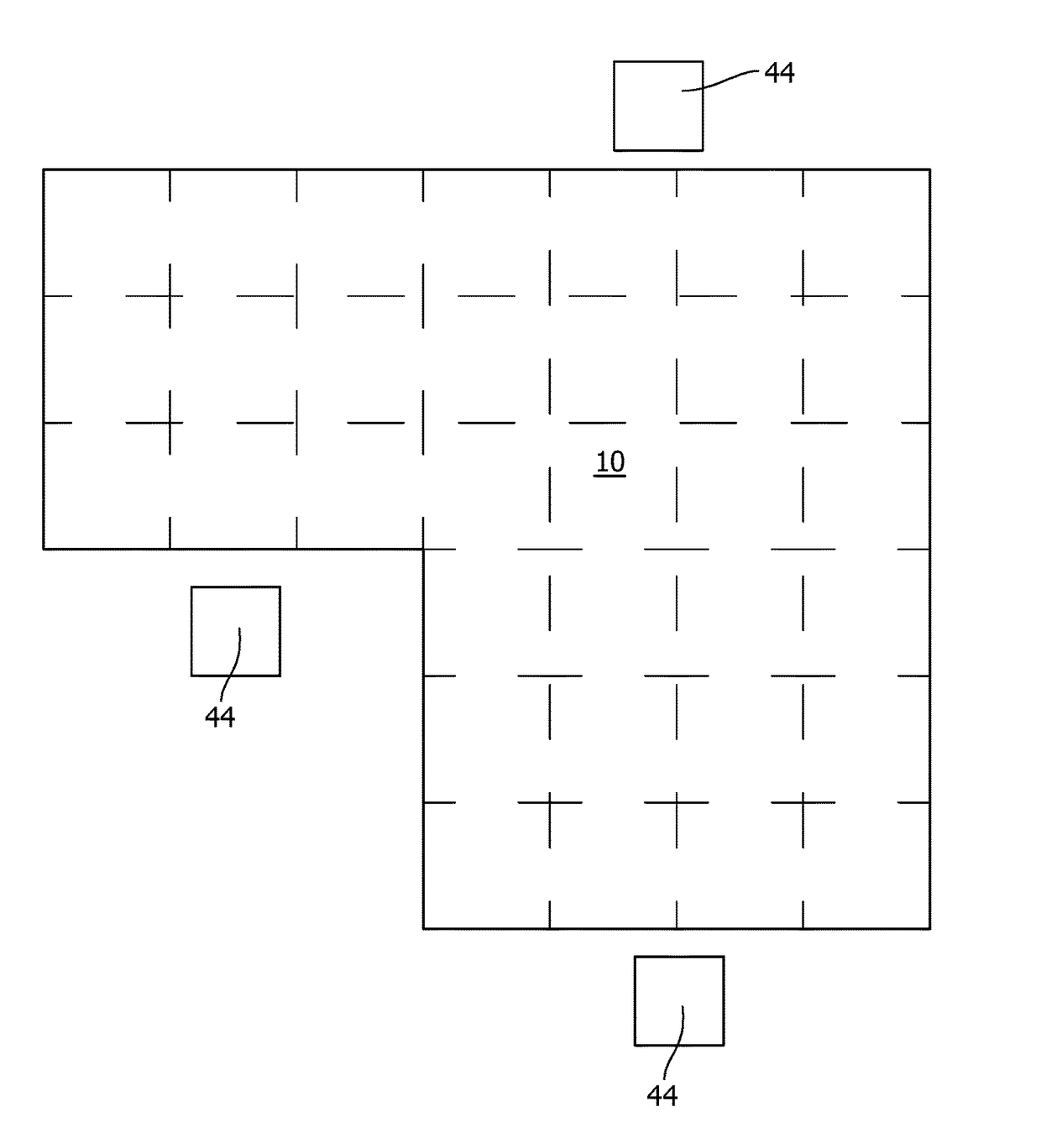
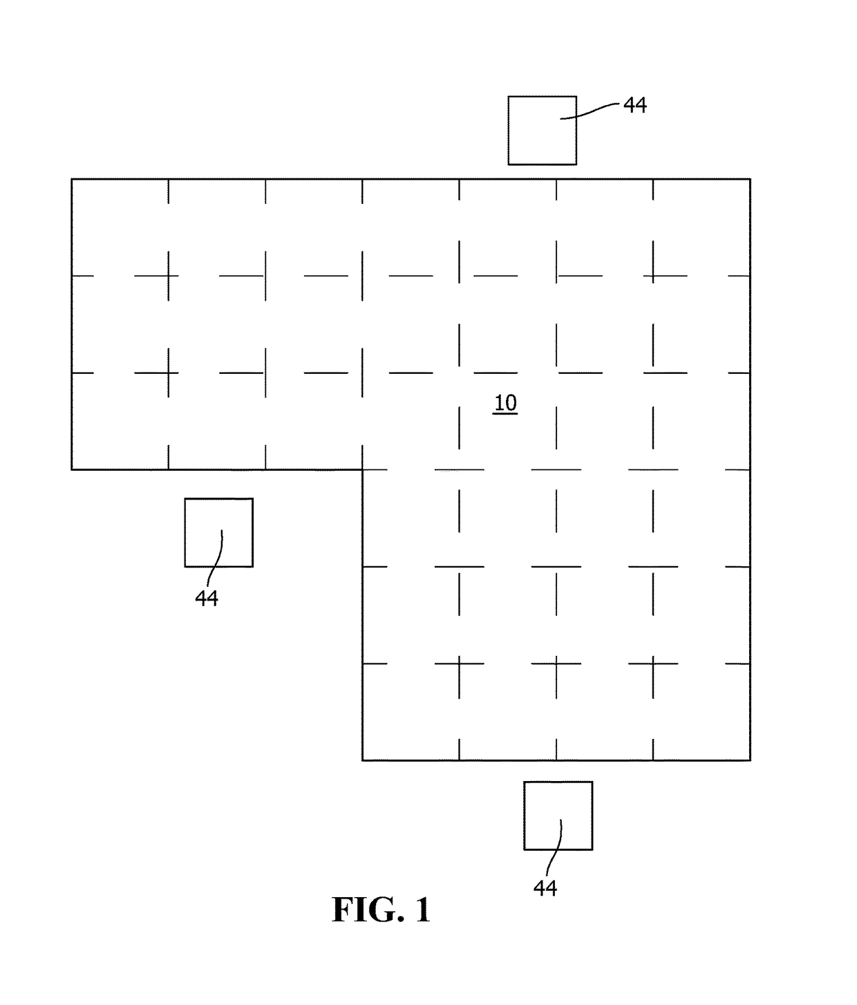
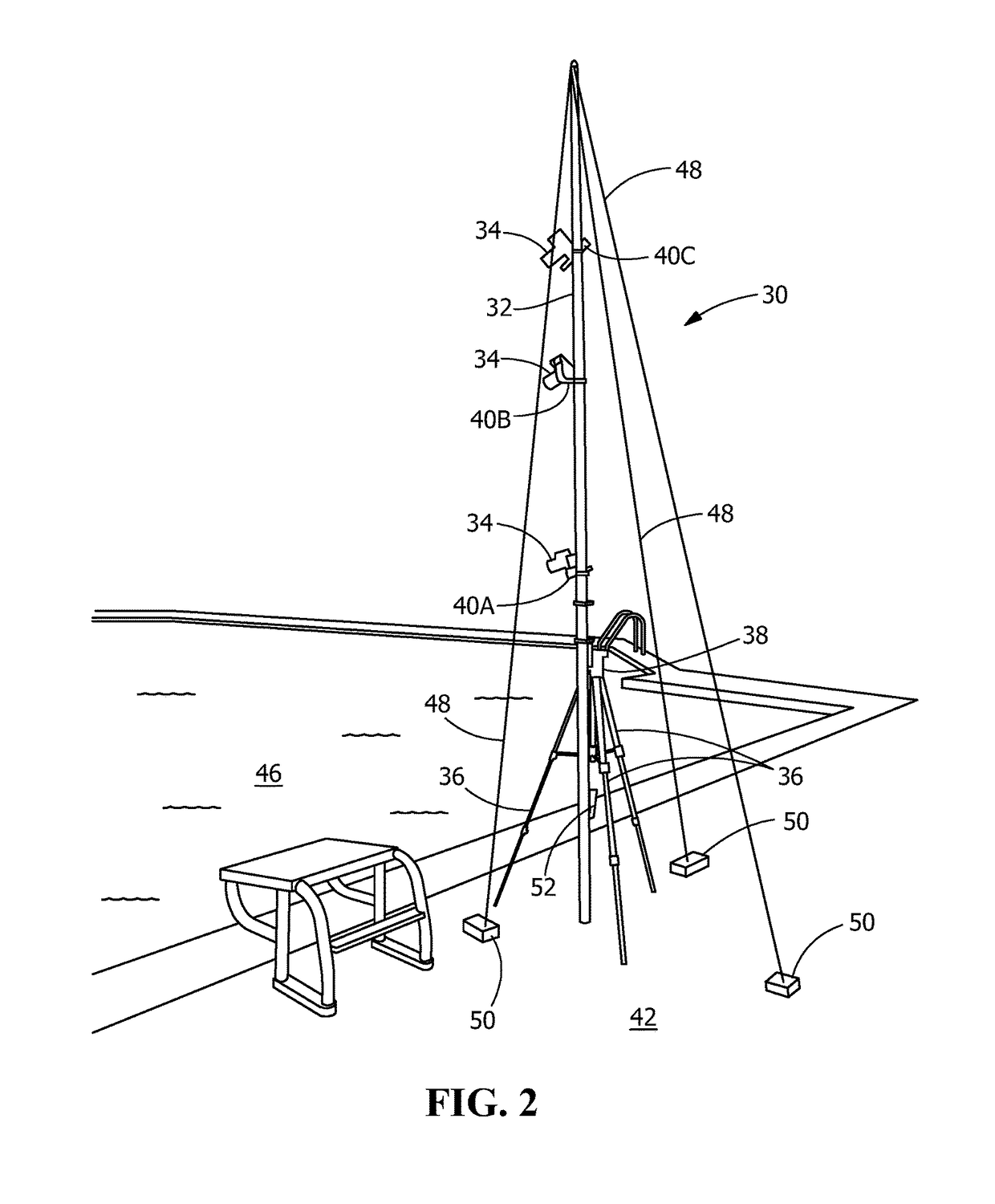
The invention is a system, equipment, and method for positioning lifeguard stations around a swimming pool or body of water to prevent drowning incidents. The system uses submersible devices and imaging devices to create a map of the pool shape and identify the best positions for lifeguard stations. This helps to minimize installation and maintenance costs and allows for critical analysis of the pool space to identify factors that affect the lifeguard's ability to supervise swimmers and recognize distress. The method involves positioning submersible devices on the pool bottom, imaging them from different locations and heights, analyzing the images to determine the best sightlines of the pool, and positioning the lifeguard stations accordingly. The invention ensures that lifeguieder can optimally position themselves to view the entire pool, reducing the risk of drowning.

Problems solved by technology

This type of monitoring is made difficult because of reflection, refraction, and water agitation, which can make it difficult to identify visually a motionless body at a depth of less than a meter when a lifeguard is not properly positioned.
The risk of drowning in a swimming pool occurs primarily when a bather is not sufficiently capable of swimming, for example in the case of a young child, or when a swimmer succumbs to a medical emergency.
In the second case, however, the swimmer may lose consciousness without attracting attention from lifeguards or nearby swimmers.
A bather who is unable to raise his head above water will experience respiratory impairment and then respiratory distress.
Without intervention, a bather in respiratory distress will progress to cardiac arrest.
In general, if aid is given between three and five minutes after consciousness has been lost, a time which nevertheless varies between individuals, the victim may survive but there is risk of irreversible brain damage.
However, a device of this type has a considerable drawback because, in order to install the sonar and connect it to the processing equipment which derives information from the echoes which are received, it is necessary to route cables through the bottom of the swimming pool and below this bottom, which leads to an entirely prohibitive cost if the pool has already been constructed.
Furthermore, the signal obtained with sonar includes echoes due to the swimming pool walls, and it is extremely difficult to eliminate the noise signal thus obtained in order to make it possible to detect the signal corresponding to the submerged body of a drowning individual.
In addition, sonar essentially makes it possible to identify the body of a drowning individual by the volume of air which it contains; if a victim has his lungs filled with water, the signal obtained will not at all conform to what might be expected and may even not be identified by the signal processing.
It will therefore be understood that a system of this type cannot be satisfactory.
In this device, the cameras only observe a layer of water parallel to the bottom, which means that the number of cameras needs to be increased if the bottom is not flat, as well as leaving most of the volume of the swimming pool unmonitored.
Furthermore, this device does not make it possible to detect motionless bodies just below the surface of the water.
Lastly, the cameras and their accessories are immersed in the swimming pool, which is unacceptable in terms of safety and causes considerable problems in connecting them to the signal processing equipment associated with them.
This device cannot therefore be satisfactory.
However, such systems are often not perfect, allowing various significant events to go undetected.
For example, it is not always possible to distinguish a shadow of a body of a swimmer passively floating, moving along the bottom, as numerous conditions must be met for the detection systems to work properly.
In correlation, this type of system is consequently particularly costly.
Consequently, confusion is possible between a shade of color (for example a shadow being carried) on the bottom of the swimming pool and a dense object close to the bottom.
Consequently, the result is that errors in detection and false initiation of the alarm systems.
In addition, the installation of complicated technology based systems is not practical in many existing swimming pools.
Existing swimming pools may not have the infrastructure to support the installation of the systems.
In addition, even if the systems could be installed, the price of installation and operation may be prohibitive.

Method used


Image

  • Lifeguard positioning system and method
  • Lifeguard positioning system and method
  • Lifeguard positioning system and method

Examples


Embodiment Construction

[0023]The description of illustrative embodiments according to principles of the present invention is intended to be read in connection with the accompanying drawings, which are to be considered part of the entire written description. In the description of embodiments of the invention disclosed herein, any reference to direction or orientation is merely intended for convenience of description and is not intended in any way to limit the scope of the present invention. Relative terms such as “lower,”“upper,”“horizontal,”“vertical,”“above,”“below,”“up,”“down,”“top” and “bottom” as well as derivative thereof (e.g., “horizontally,”“downwardly,”“upwardly,” etc.) should be construed to refer to the orientation as then described or as shown in the drawing under discussion. These relative terms are for convenience of description only and do not require that the apparatus be constructed or operated in a particular orientation unless explicitly indicated as such. Terms such as “attached,”“affi...


PUM


Abstract

A method of determining proper positioning of lifeguard stations at a swimming pool or body of water to minimize the risk of bather drowning. The method includes: positioning submersible devices or other objects on a bottom of the swimming pool or body of water according to an established grid or pattern; imaging the submersible devices from different locations and different heights at the same locations; analyzing the images and other data to determine locations and heights of the lifeguard stations which provide the best sightlines of the swimming pool from the surface of the water to the bottom of the swimming pool or body of water; and positioning the lifeguard stations at the locations and the heights determined by analyzing the data.

Description

FIELD OF THE INVENTION[0001]The present invention is a lifeguard line of sight testing method to prevent drowning incidents in swimming pool or other bodies of water. In particular, the invention is directed to a method that facilitates in the determination of the proper positioning of lifeguard stations to ensure that the lifeguards can properly see the entire pool or the assigned zone.BACKGROUND OF THE INVENTION[0002]At present, in many instances, the surveillance of swimming pools is carried out by human monitoring. This type of monitoring is made difficult because of reflection, refraction, and water agitation, which can make it difficult to identify visually a motionless body at a depth of less than a meter when a lifeguard is not properly positioned.[0003]The risk of drowning in a swimming pool occurs primarily when a bather is not sufficiently capable of swimming, for example in the case of a young child, or when a swimmer succumbs to a medical emergency. In the first case, l...

Claims


Application Information

Patent Timeline
Patent Type & Authority Patents(United States)
IPC IPC(8): G06K9/00G06T7/70H04N5/225H04N5/247H04N23/90
CPCG06T7/70H04N5/247H04N5/2251G06T2207/30232G06T2207/30208G06T7/73G06T2207/10024H04N23/50H04N23/90G06T2207/10004E04H4/14G01B11/002G01B11/0608
Inventor BELLA, MARIA
Owner ROBSON FORENSIC
Learn More