Systems and methods for implementing selective electromagnetic energy filtering objects and coatings using selectably transmissive energy scattering layers

a technology of electromagnetic energy filtering and selective electromagnetic energy, applied in the direction of optical radiation measurement, instruments, spectrometry/spectrophotometry/monochromators, etc., can solve the problems of substantially darkened tinting configuration, adversely affecting light transmissive properties, and further limited schemes

Active Publication Date: 2017-08-08
FACE INT
View PDF10 Cites 15 Cited by
  • Summary
  • Abstract
  • Description
  • Claims
  • Application Information

AI Technical Summary

Benefits of technology

[0015]It would be further advantageous to format a perceptible color, texture, image presentation of an apparent opaque light-incident side in a manner that would be adaptable to blend aesthetically with the presentation of a surrounding structure.
[0018]Exemplary embodiments may form individual laminates, coatings, films or structures in which an appearance is altered by varying an electric potential applied across the laminates, coatings, films or structures, including by modifying an electric potential applied to electrodes in the laminates, coatings, films or structures, all of which are examples of the disclosed electrically-switchable filtering or shutter components. In embodiment, an objective of such switchable layers or components may be to allow the appearance of the area behind the laminate, coating, film or structure to be masked by a wide range of chosen colors, textures and / or designs, while enhancing an appearance of an area where the laminates, coatings, films or structures are applied, positioned or placed, and allowing the transmission of substantially all wavelengths of electromagnetic energy, including energy in the visible light or near-visible light spectrum, into the area behind the laminate, coating, film or structure.
[0036]Exemplary embodiments may provide objects formed of, or including as an outer layer, at least one electrically-switchable energy filtering or shutter component incorporating a surface energy / light scattering layer that allows, in cases, the visual appearance of embedded components, including electronic data or digital display components, to be masked behind an object surface that can appear to an observer to have a predetermined surface color or a predetermined surface color pattern, or to be comprised of a predetermined surface image, which is then switchable to be completely transparent and not obscure viewing of the electronic data or digital display component, when in use.

Problems solved by technology

Thus, the principle of operation is to keep one side brightly lit rendering that side “difficult” to see through based on the principle that the reflected light masks visual penetration of the mirror from the brightly lit side.
The configuration of the substantially darkened tinting is known to adversely affect a light transmissive property, for example, when observed from an outside of the vehicle to an inside of the vehicle, which is necessarily darkened or shaded in a non-discriminant manner.
These schemes are further limited by necessarily requiring that particular dimensions of a window area to be covered are known, and the window area must be available for the view-through vinyl to be applied thereto.
A difficulty is that conventional attempts to conceal, camouflage or otherwise hide the lenses of the cameras, or the image or other energy receivers of the sensors, generally indiscriminately and / or disadvantageously modify the characteristics of the visual, or near-visual, light passing through the concealment to the cameras or sensors devices, this modification of the characteristics of the energy passing through the layer can, and generally does, adversely affect their operation in a concealed operational employment scenario.
A significant drawback to the wider proliferation of photocells used in a number of potentially beneficial operating or employment scenarios is that such “required” installations, in many instances, adversely affects the aesthetics of the structure or object on which the photocells are to be mounted for use.
To date, however, the particular implementations discussed above, and other like implementations, are all constrained in their ability to be more-broadly adapted to a far greater range of use cases based on their inherent limitations, the particular manufacturing processes by which objects including these particularized capabilities are formed, and certain attendant drawbacks in their use, particularly with regard to the manner in which the electromagnetic energy, including light in the visible and near-visible spectrum is limited, filtered, occluded or otherwise modified as it passes from an energy- or light-incident side to an opposite side of the particular structure, structural component structural outer layer.

Method used


Image

  • Systems and methods for implementing selective electromagnetic energy filtering objects and coatings using selectably transmissive energy scattering layers
  • Systems and methods for implementing selective electromagnetic energy filtering objects and coatings using selectably transmissive energy scattering layers
  • Systems and methods for implementing selective electromagnetic energy filtering objects and coatings using selectably transmissive energy scattering layers

Examples


Embodiment Construction

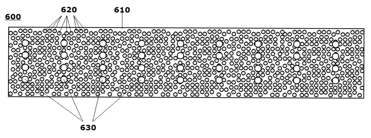
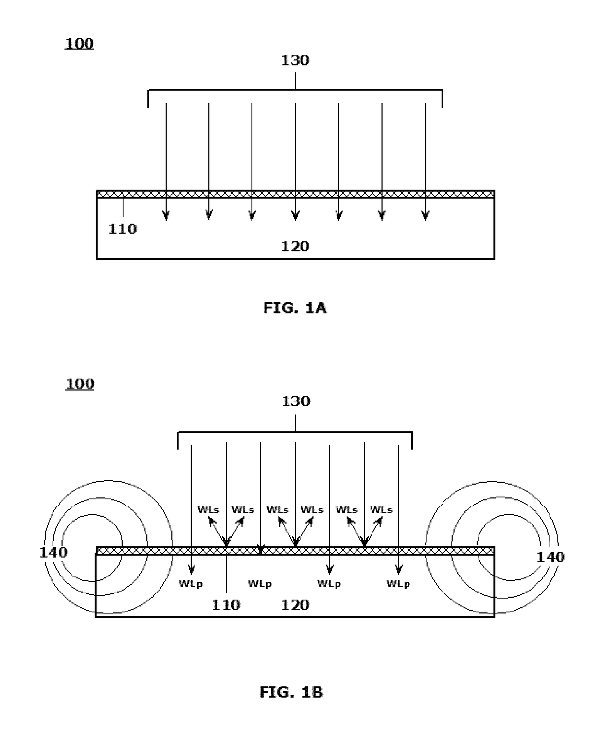
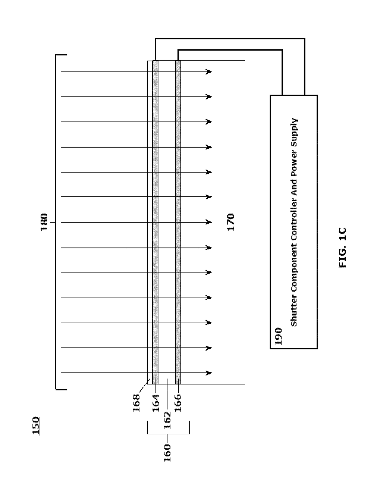
[0003]This disclosure relates to systems and methods for forming electrically-activated filter layers and shutter components including energy / light directing or scattering layers that are actively electrically switchable between a first mode in which the layers, and thus the presentation of the shutter component, appear substantially transparent (or translucent) to impinging energy when viewed from an energy / light incident side and a second mode in which the layers, and thus the presentation of the shutter component, appear opaque to the impinging energy when viewed from the energy / light incident side, by uniquely implementing energy / light directing / scattering techniques in energy / light transmissive layers, and to objects, object portions, wall plates, lenses, filters, screens and the like that are formed of, or that otherwise incorporate, such electrically-activated layers and / or shutter components.

[0004]2. Related Art

[0005]An ability to provide or promote selectable transmission o...


PUM

PropertyMeasurementUnit
diameteraaaaaaaaaa
diameteraaaaaaaaaa
particle diametersaaaaaaaaaa

Abstract

A system and method are provided for forming energy filter layers or shutter components, including energy / light directing / scattering layers that are actively electrically switchable. The energy filters or shutter components are operable between at least a first mode in which the layers, and thus the presentation of the shutter components, appear substantially transparent when viewed from an energy / light incident side, and a second mode in which the layers, and thus the presentation of the energy filters or shutter components, appear opaque to the incident energy impinging on the energy incident side. The differing modes are selectable by electrically energizing, differentially energizing and / or de-energizing electric fields in a vicinity of the energy scattering layers, including electric fields generated between a pair of transparent electrodes sandwiching an energy scattering layer. Refractive indices of transparent particles, and the transparent matrices in which the particles are fixed, are tunable according to the applied electric fields.

Description

[0001]This application claims the benefit of U.S. Provisional Patent Application No. 62 / 147,573 entitled “Photovoltaic Cell and / or Photocell With Light Scattering Layer” by Clark D. BOYD et al., filed on Apr. 14, 2015, the disclosure of which is hereby incorporated by reference herein in its entirety. This application is related to U.S. patent application Ser. No. 15 / 006,143, entitled “Systems and Methods for Producing Laminates, Laminate Layers and Coatings Including Elements for Scattering and Passing Selective Wavelengths of Electromagnetic Energy,” Ser. No. 15 / 006,145, entitled “Systems and Methods for Producing Objects Incorporating Selective Electromagnetic Energy Scattering Layers, Laminates and Coatings,” and Ser. No. 15 / 006,150 entitled “Systems and Methods for Producing Objects Incorporating Selectably Active Electromagnetic Energy Filtering Layers and Coatings,” each of which is filed on a same date as this application, the disclosures of which are hereby incorporated by ...

Claims


Application Information

Patent Timeline
Patent Type & Authority Patents(United States)
IPC IPC(8): G02F1/03G01J1/04G02F1/19G02F1/01G02F1/00G02B1/10G02B5/02G02B27/10G02B5/26G01J3/12
CPCG02B5/0242G01J1/0488G02B1/10G02B5/0263G02B5/0268G02B5/0284G02B5/0289G02B5/26G02B27/1006G02F1/0018G02F1/0102G02F1/0121G02F1/19G01J2003/1213G02F1/01G02F1/13G02F1/1675G02F1/1676G02F1/1685B60J3/04E06B9/24H01L31/02327G02B5/206H01L31/02161H01L31/02168G02B5/201B32B17/00B32B27/06B32B2255/00B32B2255/20B32B2255/26B32B2255/28B32B2307/404B32B2307/41B32B2307/412B32B2307/418B32B2457/12B32B2559/00G02B5/0247G02B2207/123Y02E10/52B82Y20/00G02F2202/36G02B5/204G02F2203/10G02F2203/22G02F1/174B32B7/02H02S40/00G06F1/16
Inventor BOYD, CLARK DFACE, BRADBURY RSHEPARD, JEFFREY D
Owner FACE INT
Why Eureka
Try Eureka