Apparatus with variable compression ratio and variable expansion ratio
a technology of compression ratio and expansion ratio, which is applied in the field of internal combustion engines, can solve the problems of limiting the application of patents, difficulty in capturing the vcr and ver internal combustion engine technology, and no commercial engine has gone, and achieves low cost, large reduction ratio, and no adverse effects on the strength of the crankshaft
- Summary
- Abstract
- Description
- Claims
- Application Information
AI Technical Summary
Benefits of technology
Problems solved by technology
Method used
Image
Examples
example 1
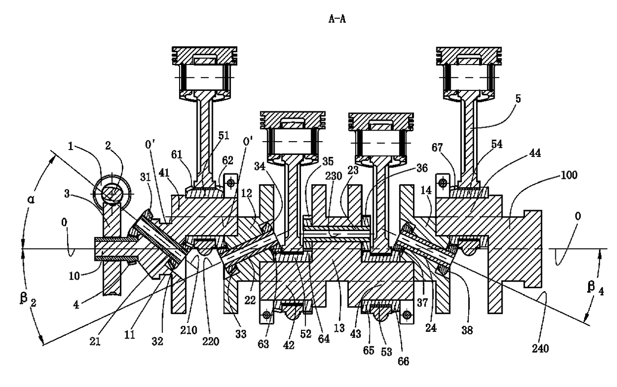
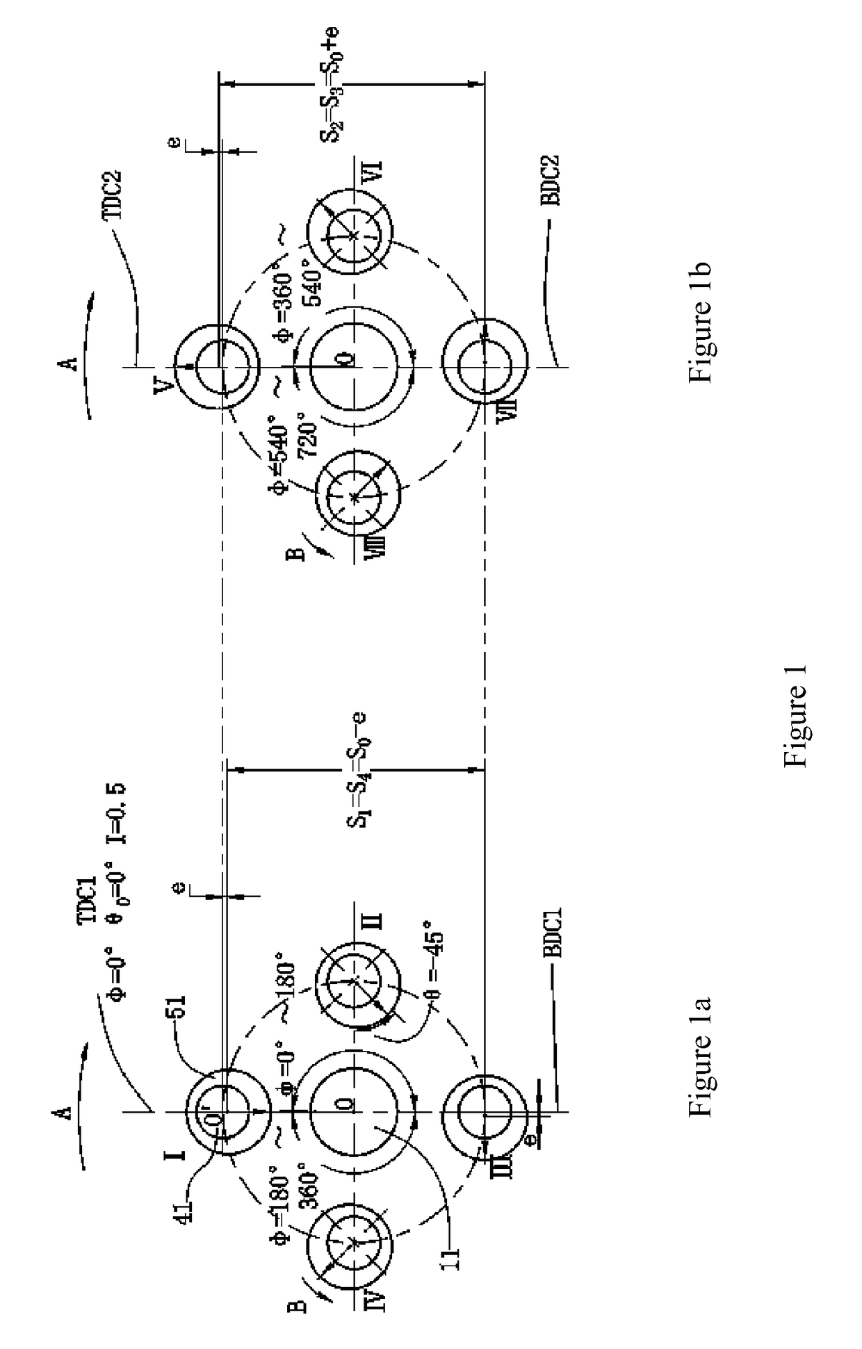
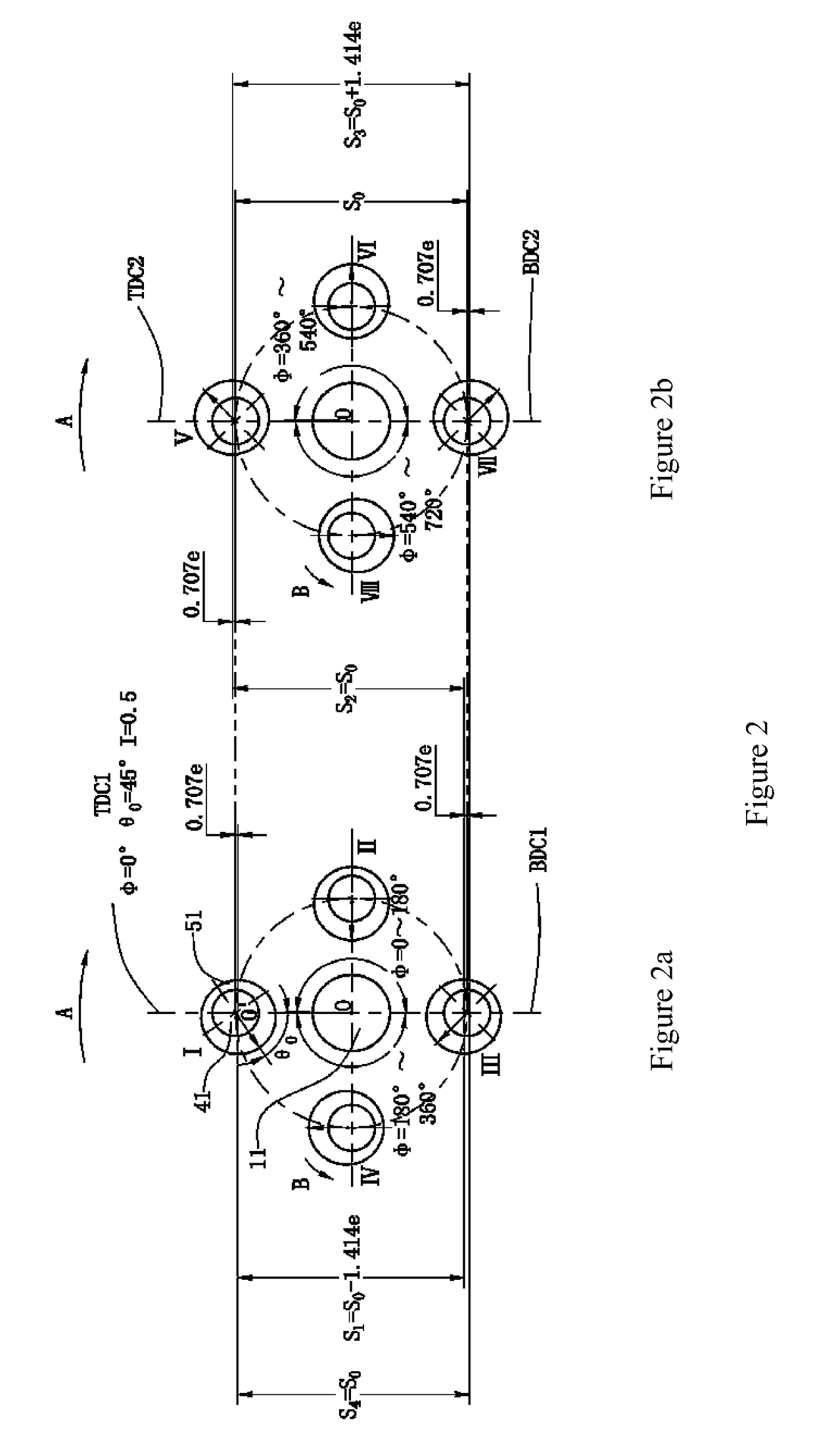
[0102]The example shows an embodiment of the present invention that is used for the four cylinder inline engine. Referring to FIGS. 6, 7, and 8, apparatus 200 with the variable expansion ratio and the variable expansion ratio is installed on the engine's crankshaft 100 and the assembly 5 of the piston connecting rod.
[0103]The assembly 5 of the piston-connecting rod is the traditional structure, it comprises piston, piston pin, connecting rod cap, connecting rod body and the big hole of the connecting rod, the piston is movably mounted within the cylinder of the internal combustion engine, the bearing bush were mounted in the big hole of the connecting rod
[0104]In order to set the eccentric sleeve on the crankpin, the crankshaft 100 adopts a split structure. The crankshaft 100 comprises the front main journal 10, the first main journal 11 and the plurality of other main journals one by one, the first crankpin 41 and the plurality of other crankpins of the following order and rear mai...
example 2
[0153]This example and embodiment is used for the four cylinder inline engine. As shown in FIGS. 11 and 12, the embodiment 2 has the same structure, transmission principle, function and role as Example 1 and embodiment 1 except for the following:
[0154]A) The axis 210 of the first transmission shaft, the axis 220 of the second transmission shaft, the axis 230 of the transmission shaft and axis 240 of the transmission shaft are all parallel with the axis 0-0 of the crankshaft 100, but do not coincide, that is: α=β4=β2=0.[0155]B) The transmission ratio I is 1:1, that is: I=(Z4 / Z31)*(Z32 / Z61)=1. In addition, in order to facilitate the transmission shafts through the main journals, make it from the front end of the main journals to reach the back end of the main journals, the diameters of the main journals are increased correspondingly.
example 3
[0156]This example and embodiment is used for the four cylinder inline engine. As shown in FIG. 13, the embodiment 3 has the same structure, transmission principle, function and role as Example 1 and embodiment 1 except for the following:
[0157]A) The axis 220 of the second transmission shaft, the axis 230 of the transmission shaft and axis 240 of the transmission shaft coincide with the axis 0-0 of the crankshaft 100.
PUM
 Abstract
Description
Claims
Application Information
 - R&D
- Intellectual Property
- Life Sciences
- Materials
- Tech Scout
- Unparalleled Data Quality
- Higher Quality Content
- 60% Fewer Hallucinations
Browse by: Latest US Patents, China's latest patents, Technical Efficacy Thesaurus, Application Domain, Technology Topic, Popular Technical Reports.
© 2025 PatSnap. All rights reserved.Legal|Privacy policy|Modern Slavery Act Transparency Statement|Sitemap|About US| Contact US: help@patsnap.com


