Flexible impeller pump

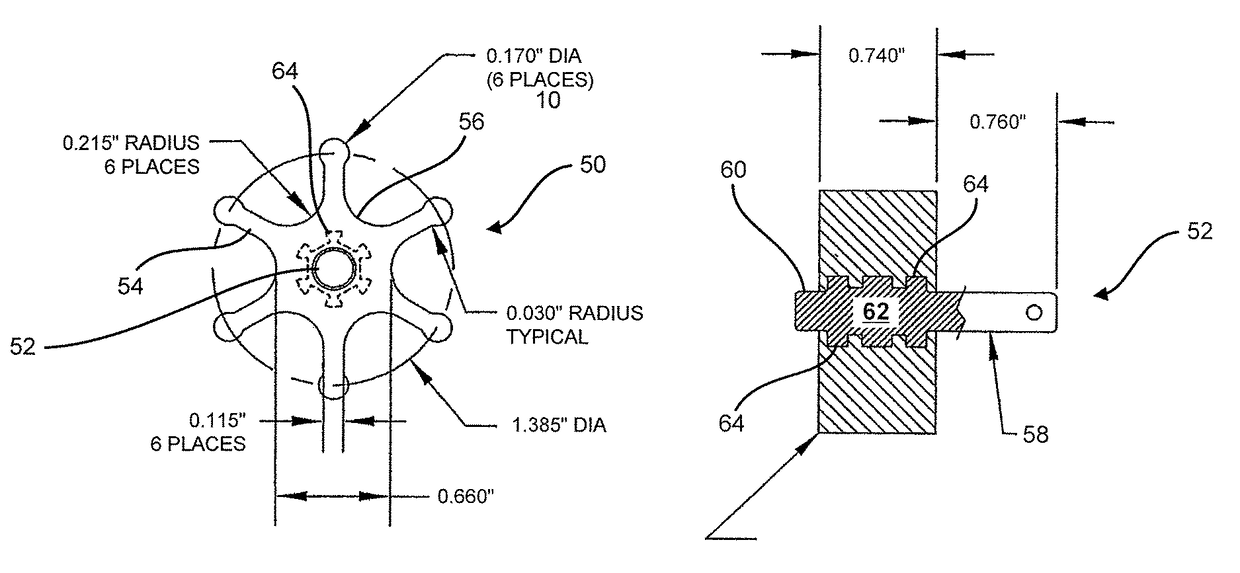
a flexible, impeller technology, applied in the direction of pump, positive displacement liquid engine, liquid fuel engine, etc., can solve the problems of reducing and affecting the service life of the flexible impeller pump. , to achieve the effect of improving the transition between the vane and the main body, reducing the amount of housing end plate wear, and improving the flexibility of the flexible impeller pump

Inactive Publication Date: 2017-08-01
AUTOMATIC BAR CONTROLS
View PDF6 Cites 2 Cited by
  • Summary
  • Abstract
  • Description
  • Claims
  • Application Information

AI Technical Summary

Benefits of technology

[0006]Improved flexible impeller pumps are disclosed. In many embodiments, wear resistant surfaces are included in the flexible impeller pump such that each end face of the flexible impeller is immediately adjacent to one of the wear resistant surfaces. In many embodiments, the flexible impeller pump includes an impeller shaft that includes an impeller interface portion having one or more protruding portions shaped to interlock with the flexible impeller. And in many embodiments, the flexible impeller pump includes a flexible impeller with improved vane to main body transitions. The wear resistant surfaces decrease the amount of housing end plate wear that occurs, especially when the flexible impeller pump is used to transfer fluids having abrasive components. The wear resistant surfaces may also support the use of moldable housing materials, such as plastic. The one or more protruding portions of the impeller shaft provide a more secure coupling between the impeller shaft and the flexible impeller as compared to existing flexible impeller / shaft assemblies. The more secure coupling is especially beneficial when the flexible impeller pump is used to pump hot abrasive fluids, which may tend to cause the flexible impeller to get hot and become detached from the impeller shaft in existing flexible impeller / shaft assemblies.

Problems solved by technology

Existing flexible impeller pumps, however, suffer from a variety of common problems.
For example, as illustrated in FIG. 2, the repetitive bending of the flexible vanes can lead to fracture of the vanes and / or permanent bowing of the vanes.
The sliding of the tips of the flexible vanes along the sidewalls of the housing, especially along the sidewall of the cam portion, can lead to localized wearing, pitting, and / or ripping of the tips of the flexible vanes.
In addition, relative motion between the end faces of the impellor and adjacent end walls of the housing can result in additional wear damage to the housing end walls.
The plastic end walls of such pump housings can experience significant amounts of wear due to the presence of such abrasive components.

Method used


Image

  • Flexible impeller pump
  • Flexible impeller pump
  • Flexible impeller pump

Examples


Embodiment Construction

[0035]In the following description, various embodiments of the present invention will be described. For purposes of explanation, specific configurations and details are set forth in order to provide a thorough understanding of the embodiments. However, it will also be apparent to one skilled in the art that the present invention may be practiced without the specific details. Furthermore, well-known features may be omitted or simplified in order not to obscure the embodiment being described.

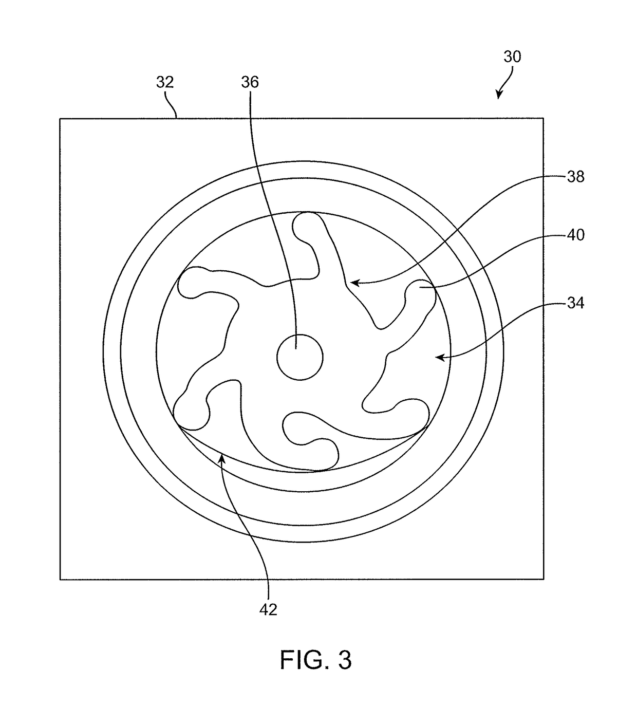
[0036]Referring now to the drawings, in which like reference numerals represent like parts throughout the several views, FIG. 3 shows the configuration of an existing flexible impeller pump 30. The impeller pump 30 includes a housing 32 defining an opening 34, an impeller shaft 36 mounted to rotate relative to the housing 32, and a flexible impeller 38 mounted to the impeller shaft 36 to be rotated by the impeller shaft 36. The flexible impeller 38 includes vanes 40 that extend radially from a cyl...


PUM


Abstract

A flexible impeller pump includes improved flexible impeller geometry, an impeller shaft having protruding portions that produce a stronger and more durable connection between the impeller shaft and the flexible impeller, a smoother housing cam surface, and wear resistant surfaces that are disposed between end faces of the flexible impeller and adjacent housing end walls.

Description

BACKGROUND[0001]Flexible impeller pumps are often used to pump fluids. In the flexible impeller pump 10 illustrated in FIG. 1, an impellor 12 having flexible vanes 14 extending radially from a central hub is mounted for rotation within an opening of a housing 16. The impellor 12 is mounted to a shaft, which is mounted for rotation relative to the housing 16 about an axis. The opening is in fluid communication with an inlet 18 and an outlet 20. As the impellor 12 is rotated (clockwise relative to the view direction of FIG. 1), tips of the flexible vanes interface with sidewalls of the opening to draw fluid from the inlet 18 and discharge the fluid to the outlet 20. The housing includes a cam portion 22, which has a sidewall that is disposed closer to the axis than the other sidewalls of the opening, thereby causing increased bending of the flexible vanes 14 as they pass by the cam portion 22. As the impellor 12 rotates, each flexible vane 14 exits the cam portion 22 in the vicinity o...

Claims


Application Information

Patent Timeline
Patent Type & Authority Patents(United States)
IPC IPC(8): F04B35/04F04C5/00
CPCF04C5/00F04C2240/802F04C2270/16F05C2203/08
Inventor SALMELA, JUHA K.TUYLS, JAMES M.MARTINDALE, RICHARD A.
Owner AUTOMATIC BAR CONTROLS
Why Eureka
Try Eureka