
Portable water inflatable barrier with water inflatable base

a portable, barrier technology, applied in the direction of dykes, marine site engineering, construction, etc., can solve the problems of time-consuming and costly disposal of sandbags, significant cost and construction time associated with a dike, and achieve the effect of simple and inexpensive removal

Active Publication Date: 2017-08-01
ABELES GARY E
View PDF41 Cites 9 Cited by
  • Summary
  • Abstract
  • Description
  • Claims
  • Application Information

AI Technical Summary

Benefits of technology

The invention is a portable, water inflatable barrier that can be easily moved to construction sites and filled with water to create a temporary wall or dike. It is made of light, flexible material and has an internal structure similar to a sandbag wall. The barrier is a single unit that includes shaping and internal partitions to create a complex structure. The cells have valves that prevent the water from leaking out if there is a puncture. The outer shell of the barrier is made of a thicker material to resist puncture. The barrier's internal structure makes it able to maintain its shape when exposed to external forces and includes stiff rods or plates to increase its rigidity. The technical effects of the invention are that it is simple, inexpensive, and easy to assemble or remove.

Problems solved by technology

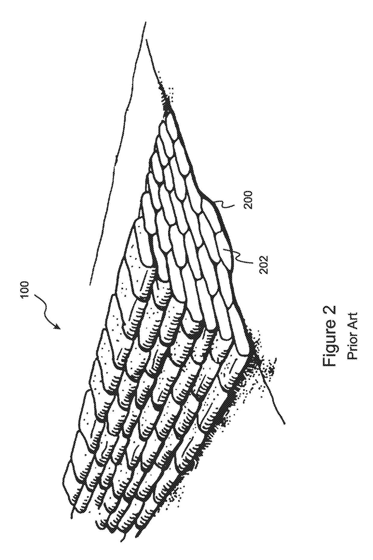
While a sandbag barrier is generally effective and the materials are relatively inexpensive, there can be significant costs and construction time associated with a sandbag dike, due to the requirement to bring the sand or dirt to the construction site, which may weigh many tons, and due to the need to employ significant labor to fill and stack the bags.
In addition, after the flood or other threat has subsided, disposal of the sandbags can be time consuming and costly, especially if the sand and bags have become wet and contaminated by flood water and require special disposal procedures to avoid risks to health and to the environment.

Method used


Image

  • Portable water inflatable barrier with water inflatable base
  • Portable water inflatable barrier with water inflatable base
  • Portable water inflatable barrier with water inflatable base

Examples


Embodiment Construction

[0059]With reference to FIG. 3, the present invention is a portable, water inflatable barrier 300 that has a structure similar to a sandbag dike or wall 100 and functions in a similar manner, but does not require delivery of large quantities of heavy materials to the construction site, does not require large amounts of labor to assemble, and is simple and inexpensive to remove when no longer needed. The barrier 300 is made of a light, flexible material, such as a heavy plastic for nanofiber, and can be transported to the construction site in a deflated state, after which it is positioned and filled with locally available water. In embodiments, the barrier material is coated with a material such as tyvec or liquid rubber that will tend to seal any puncture of the material that may occur.

[0060]FIG. 3 illustrates an embodiment of a first general aspect of the present invention in which the barrier is a single unit 300 that includes shaping and internal partitions which create an overal...


PUM


Abstract

A portable, water-filled barrier system includes a barrier internally divided into cells that emulates a section of a sandbag dike or wall. Automatic valves can seal openings between the filled cells, so that a punctured cell will not cause cells below and behind to deflate. In embodiments the barrier can be initially filled with air, positioned, and then filled with water while the air escapes through a pressure valve. The system further includes a base with water inflatable front and back panels. The side panels and bottom panel of the base can be water inflatable or flat. The base can be used to increase friction with the ground, protect against stones, and / or to support a leveling wedge or leveling material such as sand or spray foam when located on a sloped surface. A plurality of adjacent bases and barriers can provide an extended barrier system.

Description

RELATED APPLICATIONS[0001]This application is a continuation in part of application Ser. No. 15 / 016,606, filed on Feb. 5, 2016, now U.S. Pat. No. 9,556,574. Application Ser. No. 15 / 016,606 is a continuation of application Ser. No. 14 / 594,407, filed on Jan. 12, 2015, now U.S. Pat. No. 9,334,616. Application Ser. No. 14 / 594,407 is a continuation in part of application Ser. No. 13 / 663,756, filed on Oct. 30, 2012, now U.S. Pat. No. 8,956,077. Application Ser. No. 13 / 663,756 claims the benefit of U.S. Provisional Application No. 61 / 553,403, filed Oct. 31, 2011. All of these applications are herein incorporated by reference in their entirety for all purposes.FIELD OF THE INVENTION[0002]The invention relates to temporary barriers, such as dikes used for flood control, and more particularly, to water-filled portable barriers.BACKGROUND OF THE INVENTION[0003]Circumstances sometimes arise where a temporary dike, wall, or other barrier is needed to prevent a flood, landslide, or other threat f...

Claims


Application Information

Patent Timeline
Patent Type & Authority Patents(United States)
IPC IPC(8): E02B3/10E02B7/00E02B3/16
CPCE02B3/108E02B3/106E02B3/16E02B7/005E02B3/127
Inventor ABELES, GARY E
Owner ABELES GARY E
Learn More