
Portable water inflatable barrier integral with support base

a technology of inflatable barriers and support bases, applied in the field of temporary barriers, can solve the problems of time-consuming and costly disposal of sandbags, significant cost and construction time associated with sandbag dikes,

Pending Publication Date: 2022-07-21
ABELES GARY E
View PDF10 Cites 0 Cited by
  • Summary
  • Abstract
  • Description
  • Claims
  • Application Information

AI Technical Summary

Benefits of technology

The invention is a portable and modular barrier system that can be inflated with water and used to protect construction sites. It is made up of light and flexible modules that can be easily transported and positioned. The barrier is simple and cost-effective to remove when no longer needed. Overall, the invention allows for efficient and effective protection during construction without needing to deliver large loads of heavy materials or hire large amounts of labor.

Problems solved by technology

However, there can be significant costs and construction time associated with a sandbag dike, due to the requirement to bring the sand or dirt to the construction site, which may weigh many tons, and due to the need to employ significant labor to fill and stack the bags.
In addition, after the flood or other threat has subsided, disposal of the sandbags can be time consuming and costly, especially if the sand and bags have become wet and contaminated by flood water and require special disposal procedures to avoid risks to health and to the environment.

Method used


Image

  • Portable water inflatable barrier integral with support base
  • Portable water inflatable barrier integral with support base
  • Portable water inflatable barrier integral with support base

Examples


embodiment 500

[0051]With reference to FIG. 5, in some embodiments 500 the cells 302 include passive automatic valves 500 that seal the passages 400 after the cells 302 are filled with water, so that deflation of one cell due to a puncture or some other cause will not cause the cells beneath it to deflate. In the embodiment 500 of FIG. 5, the valves 502 are flaps of elastic material joined to the upper surfaces of the cells 302 by living hinges 504. A small air bladder 506 is included in the region of the valve 502 that is positioned to cover the passage 400. When the cell 302 is empty, gravity causes the valve 502 to fall away from the passage 400, so that the cell 302 can fill with water. However, once the cell 302 is full of water, the air bladder 506 lifts the valve 502 into place and closes the passage 400. Once the valves 502 are closed, if a cell should develop a leak and deflate, only the cells directly above it will be affected.

[0052]In addition, the embodiment 500 of FIG. 5 includes late...

embodiment 700

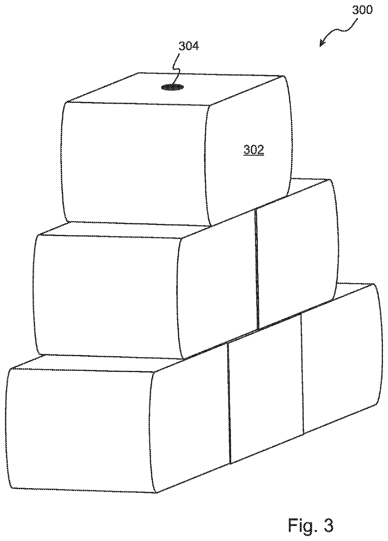
[0055]FIG. 7 is a perspective rear view of an embodiment 700 similar to FIG. 6, except that the loops 604 are located on both the front-facing and rear-facing surfaces of the modules 300, and a single, continuous strap 702 is passed through the loops 604 and around the modules 300 so as to attach the modules 300 and form the barrier 700. The embodiment of FIG. 7 also includes a manifold 704 that can be used to fill all of the modules 300 simultaneously through fill-ports provided in the bases of the modules 300.

[0056]With reference to FIG. 8, in some embodiments the barrier modules 800 have interlocking ends that provide structural cooperation and a water-tight seal between adjacent modules. FIG. 8 is a perspective view of a single module 800 that is three cells wide. The module includes alternate rows of cells 802 that extend from the ends by a length of one cell, while the interleaved rows 804 do not. The opposite pattern is provided on the other end of the module 800. It can be s...


PUM


Abstract

A portable, water-filled barrier system includes a water-fillable module that is internally divided into cells that emulate a section of a sandbag dike or wall, the module being fixed to an underlying base having front and rear boundaries that extend up from base and horizontally restrain the module. The base can be flexible and water filled, or rigid, and can be installed at or below grade. A lid can extend between the front and rear boundaries of a rigid base to cover the unfilled module, enabling the assemblies to be stacked when stored and transported. The lid can be hinged and, when open, can be supported by at least one brace extending from behind the lid to underlying terrain, where it can be wedged or staked in place. Adjacent bases can be joined at the front and rear to maintain contact between adjacent modules.

Description

RELATED APPLICATIONS[0001]This application is a continuation in part of U.S. application Ser. No. 17 / 008,980, filed on Sep. 1, 2020. Application Ser. No. 17 / 008,980 is a continuation in part of application Ser. No. 16 / 525,872, filed on Jul. 30, 2019, now U.S. Pat. No. 10,767,329. Application Ser. No. 16 / 525,872 is a continuation in part of application Ser. No. 16 / 016,874, filed on Jun. 25, 2018, now U.S. Pat. No. 10,400,408. Application Ser. No. 16 / 016,874 is a continuation in part of application Ser. No. 15 / 630,457, filed on Jun. 22, 2017, now U.S. Pat. No. 10,036,134. Application Ser. No. 15 / 630,457 is a continuation in part of application Ser. No. 15 / 382,965, filed on Dec. 19, 2016, now U.S. Pat. No. 9,719,225. Application Ser. No. 15 / 382,965 is a continuation in part of application Ser. No. 15 / 016,606, filed on Feb. 5, 2016, now U.S. Pat. No. 9,556,574. Application Ser. No. 15 / 016,606 is a continuation of application Ser. No. 14 / 594,407, filed on Jan. 12, 2015, now U.S. Pat. No....

Claims


Application Information

Patent Timeline
IPC IPC(8): E02B3/10E02B3/12E02B7/00
CPCE02B3/108E02B7/005E02B3/127E02B3/04
Inventor ABELES, GARY E.
Owner ABELES GARY E
Learn More