
Pneumatic power and drag system

a pneumatic power and drag technology, applied in the field of pneumatic power and drag system, can solve the problems of affecting the work efficiency of the system, the cost of producing such a system is typically more expensive than the cost of conventional combustion motors, and the battery which supplies current to the electric motor may only be recharged

Inactive Publication Date: 2017-08-01
ANTROBUS CRAIG
View PDF9 Cites 14 Cited by
  • Summary
  • Abstract
  • Description
  • Claims
  • Application Information

AI Technical Summary

Benefits of technology

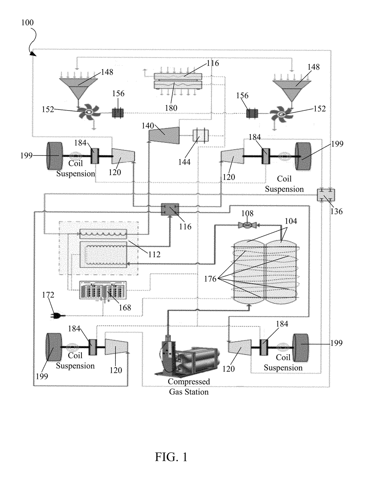
The present invention is about a power system for vehicles that uses pneumatic power to reduce power consumption and improve efficiency. The invention is a system that uses air to create power, which can then be used to move the vehicle's wheels. This system is more efficient than traditional combustion motors and electric motors, and it can also be used in conjunction with other systems to further improve performance. The invention includes a pneumatic power and drag reduction system architecture, operational component diagrams, and a method for using the system in a vehicle. Overall, the invention provides a more optimal approach for powering vehicles and improving their performance.

Problems solved by technology

Conventional combustion motors may include a combustible liquid such as petrol, wherein an expansive force from heating the liquid may cause a piston of the engine to move, and thus creating work.
With conventional electric motors, a cost to produce such a system may typically be more expensive than the conventional combustion motor.
Moreover, the battery which supplies current to the electric motor may only be recharged by plugging the battery into a power supplying station.
In view of the foregoing, it is clear that these traditional techniques are not perfect and leave room for more optimal approaches.

Method used


Image

  • Pneumatic power and drag system
  • Pneumatic power and drag system
  • Pneumatic power and drag system

Examples


Embodiment Construction

[0017]The present invention is best understood by reference to the detailed figures and description set forth herein.

[0018]It is to be understood that any exact measurements / dimensions or particular construction materials indicated herein are solely provided as examples of suitable configurations and are not intended to be limiting in any way. Depending on the needs of the particular application, those skilled in the art will readily recognize, in light of the following teachings, a multiplicity of suitable alternative implementation details.

[0019]In some embodiments, the pneumatic power system may also work in conjunction with electric motors. The electric motors may provide electricity to components used in the pneumatic power system. This feedback functionality may make the pneumatic powering system more efficient and thus the cost of travel may be quite inexpensive as compared to conventional passenger vehicles.

[0020]It may be contemplated that in many embodiments, a cost to man...


PUM


Abstract

Power systems, heat exchanger systems, electrical regeneration systems and air drag reduction systems for a wheeled vehicle are provided. The systems comprise a vehicle that includes a compressed air system and electrical system. The power and drag reduction system also comprises a plurality of pneumatic motors, one each connected to each wheel, the pneumatic motors using compressed air to drive each wheel. The electrical system supports vehicle braking and regenerates electricity for vehicle batteries. A heat exchanger heats expanding air and is configured to substantially evenly distribute said heated air to the pneumatic motors. Air from a front grill is diverted to impellers that turn electric generators to regenerate power and reduce drag. A drag reducing arrangement blending mirrors with camera into the vehicle body is included as is a plug-in 120-volt trickle charge system and a quick charge (DC) system for battery charging.

Description

FEDERALLY SPONSORED RESEARCH OR DEVELOPMENT[0001]Not applicable.COPYRIGHT NOTICE[0002]A portion of the disclosure of this patent document contains material that is subject to copyright protection by the author thereof. The copyright owner has no objection to the facsimile reproduction by anyone of the patent document or patent disclosure for the purposes of referencing as patent prior art, as it appears in the Patent and Trademark Office, patent file or records, but otherwise reserves all copyright rights whatsoever.BACKGROUND OF THE RELEVANT PRIOR ART[0003]One or more embodiments of the invention generally relate to a power system. More particularly, certain embodiments of the invention relates to a vehicle power system.[0004]The following background information may present examples of specific aspects of the prior art (e.g., without limitation, approaches, facts, or common wisdom) that, while expected to be helpful to further educate the reader as to additional aspects of the prio...

Claims


Application Information

Patent Timeline
Patent Type & Authority Patents(United States)
IPC IPC(8): B60K6/00B60K1/02B60K17/356B60L7/10B60K3/04B60L11/18B62D35/00B60H1/00B60R1/00
CPCB60K6/00B60K17/356B60K1/02B60L7/10B60K3/04B60L11/1809B62D35/00B60H1/00328B60R1/00B60R2300/00B60L1/003B60L1/02B60L1/20B60L7/18B60L8/006B60Y2400/15B60K1/04B60K7/0007B60K7/0023B60K15/07B60K2001/005B60K2001/008B60K2007/0092B60K2015/0632B60K2015/0633B60K2016/006B60Y2400/204B60Y2300/18125Y02T10/90B60K2006/123Y02T10/7072Y02E10/72F03D9/25
Inventor ANTROBUS, CRAIGDINCER, IBRAHIMZADEH, REZA MOHAMMADALIZAMFIRESCU, CALIN
Owner ANTROBUS CRAIG
Learn More