
Ball chair

a ball chair and seat technology, applied in the field of chairs, can solve the problems of user's danger of sitting on the ball chair, the back and the seat are difficult to join, and the user's back and seat are separated, so as to achieve the effect of easy assembly and firm structur

Active Publication Date: 2017-07-25
CHIA LIN SPORT
View PDF13 Cites 11 Cited by
  • Summary
  • Abstract
  • Description
  • Claims
  • Application Information

AI Technical Summary

Benefits of technology

The design results in a firm, easy-to-assemble ball chair that is more comfortable and safer for users, with enhanced structural integrity and ergonomic conformity.

Problems solved by technology

However, in some conventional ball chairs, the juncture of the back and the seat is too complicated in structure, resulting in difficulty in assembling the back and the seat with each other.
In other conventional ball chairs, the connecting strength between the back and the seat may be not strong enough to withstand the pressure exerting on the back of the ball chair by the back of the user who sits on the ball chair and leans his / her back on the back of the ball chair, resulting in that the juncture of the back and the seat is liable to have structural damage or even resulting in separation of the back from the seat.
This brings the user who sits on the ball chair a certain danger.
Besides, the circular-ball-shaped cushion of the conventional ball chair is too different in shape from the hips of the user to conform with ergonomics, resulting in uncomfortableness of the user.

Method used


Image

  • Ball chair
  • Ball chair
  • Ball chair

Examples


Embodiment Construction

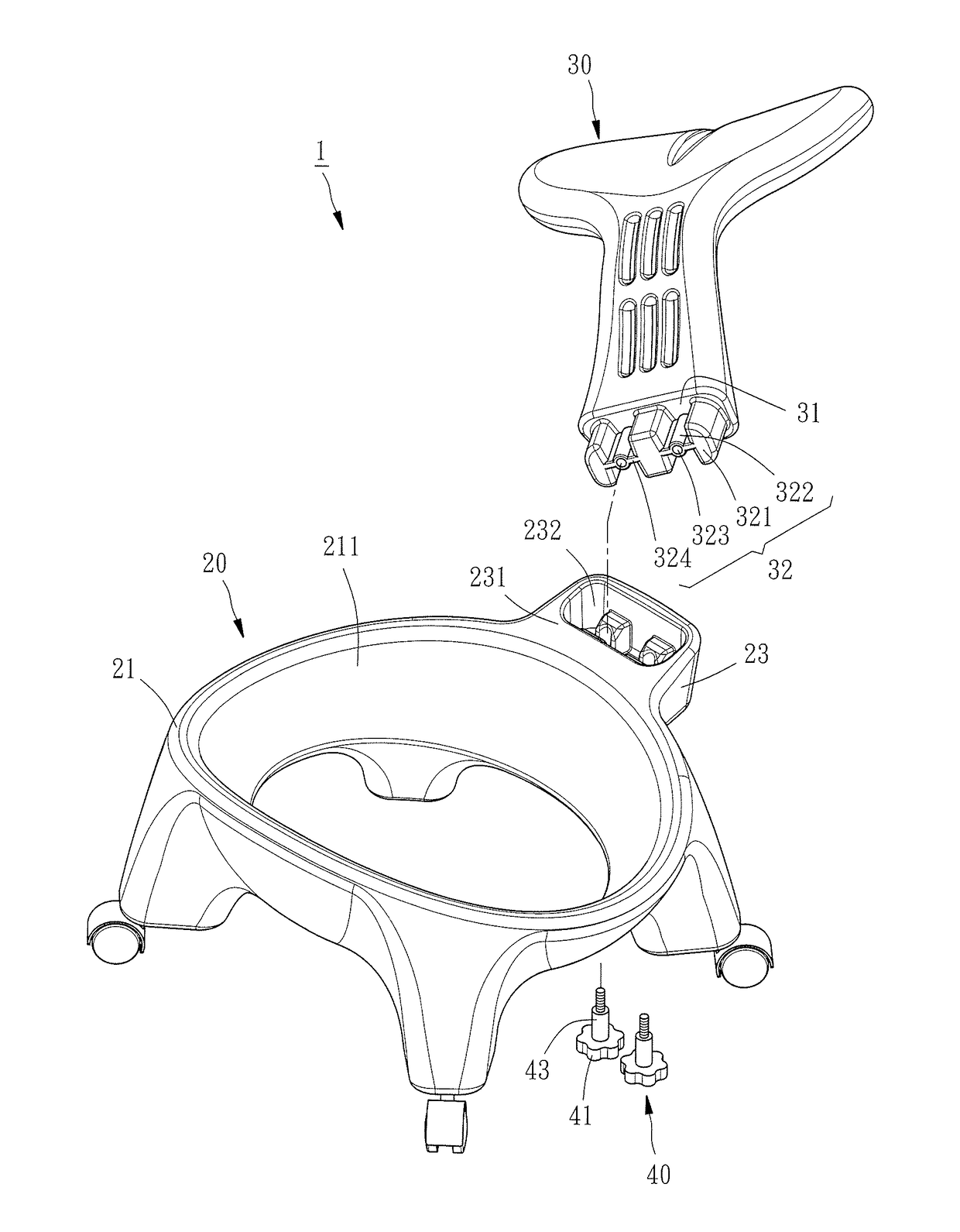
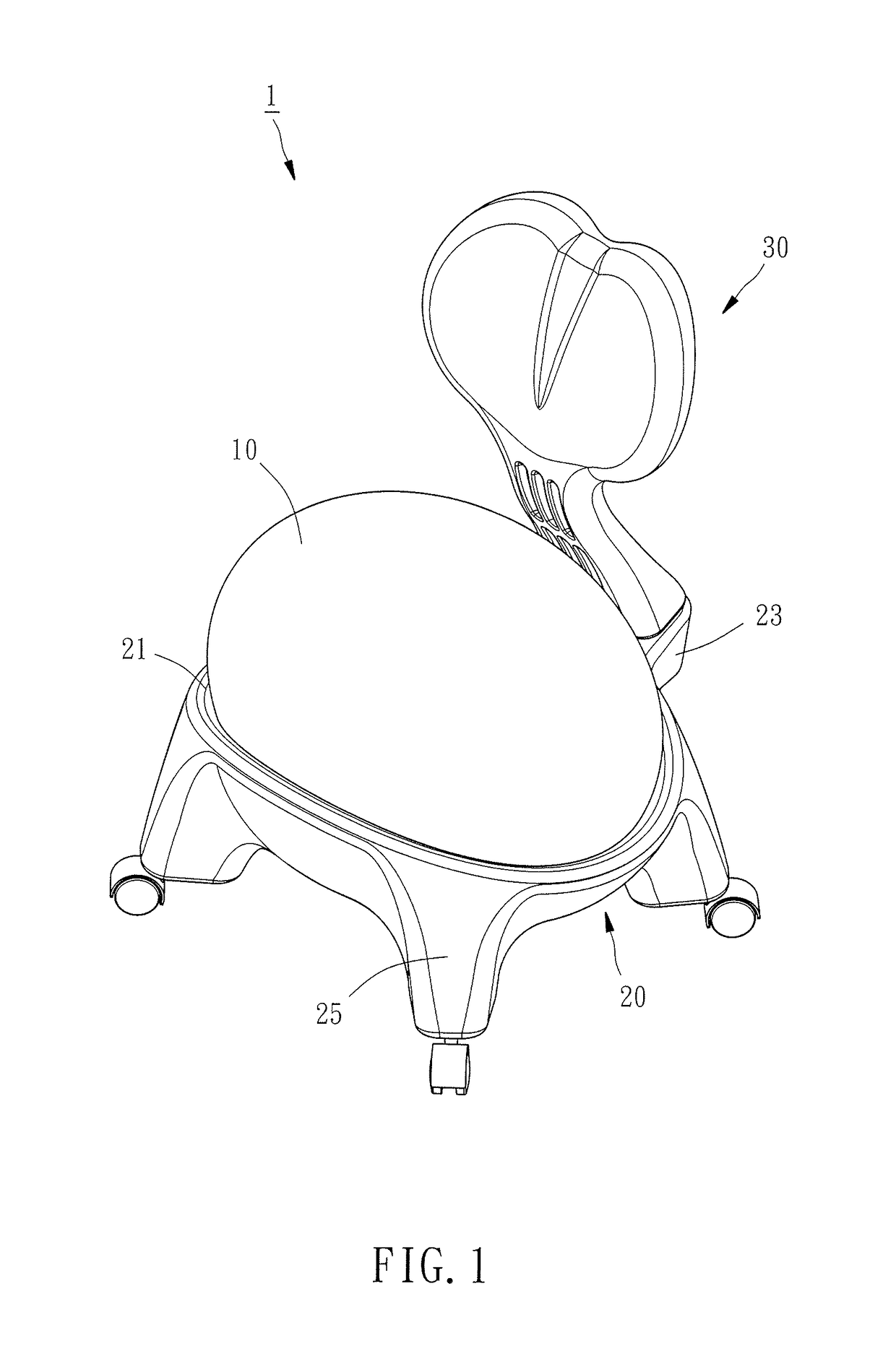
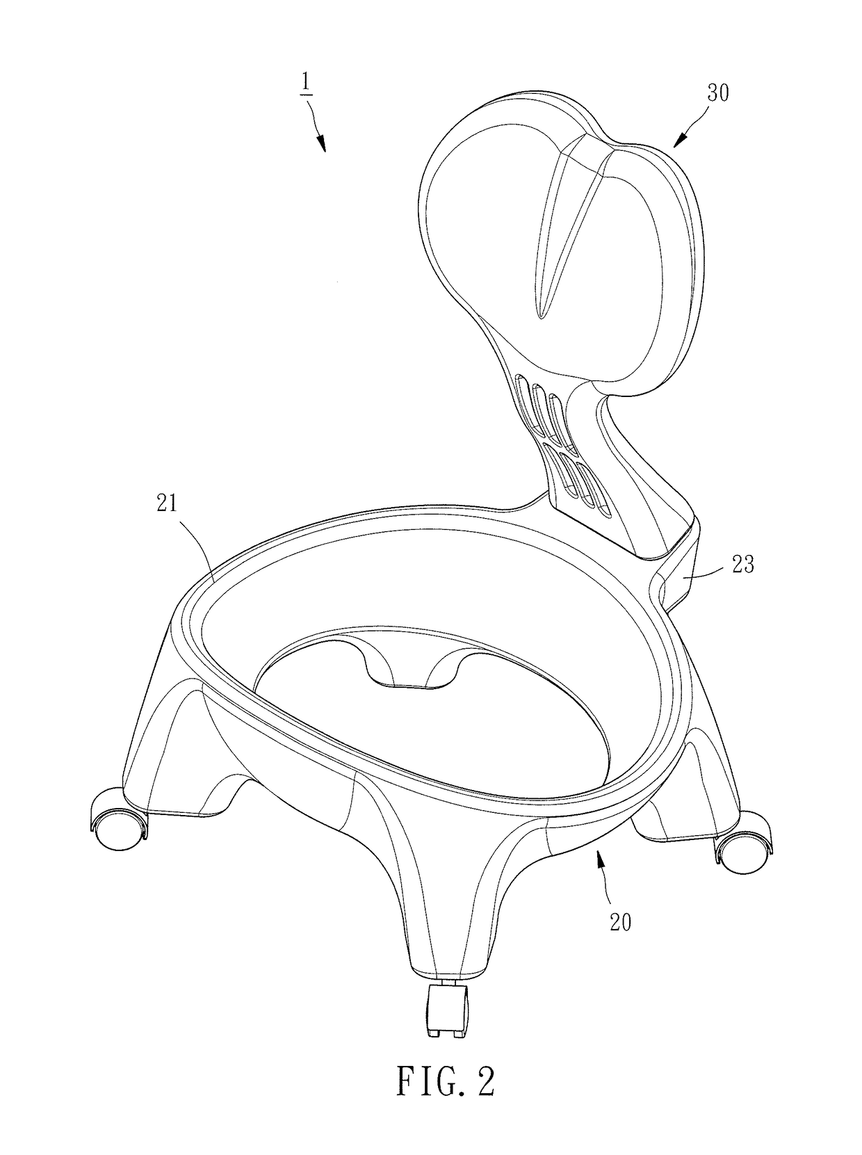
[0015]Referring to FIGS. 1-6, a ball chair 1 according to an embodiment of the present invention is shown comprising a cushion 10, a seat 20, a back 30, and two threaded fastening members 40.

[0016]The cushion 10 has a ball shape. In this embodiment, the cushion 10 is approximately shaped like an elliptic ball.

[0017]The seat 20 has a bearing portion 21 for supporting the cushion 10, a connecting portion 23 connected to the rear side of the bearing portion 21, and four feet 25 extending downwards from the peripheral of the bearing portion 21. As shown in FIG. 6, the connecting portion 23 has a lower stop surface 231 at the top thereof, an engaging recess 232 concaved from the lower stop surface 231, and two through holes 233 substantially perpendicularly penetrating through the bottom of the connecting portion 23 and communicating with the engaging recess 232. Wherein, the engaging recess 232 has three relatively larger cavities 234, two relatively smaller cavities 235 each located be...


PUM


Abstract

A ball chair includes a ball-shaped cushion, a seat, a back and at least a threaded fastening member. The seat has a bearing portion for bearing the cushion, and a connecting portion connected with the bearing portion and having an engaging recess and at least a through hole communicating with the engaging recess. The back has an engaging block inserted in the engaging recess and having at least two relatively larger protrusions, at least a relatively smaller protrusion located between the two relatively larger protrusions, and at least a threaded hole provided in the relatively smaller protrusion and corresponding in position to the through hole. The threaded fastening member is inserted through the through hole and fixed in the threaded hole to fix the back to the seat.

Description

BACKGROUND OF THE INVENTION[0001]1. Field of the Invention[0002]The present invention relates generally to chairs and more particularly, to a ball chair.[0003]2. Description of the Related Art[0004]The conventional ball chair is primarily composed of a back, a seat, and a circular-ball-shaped cushion. However, in some conventional ball chairs, the juncture of the back and the seat is too complicated in structure, resulting in difficulty in assembling the back and the seat with each other. In other conventional ball chairs, the connecting strength between the back and the seat may be not strong enough to withstand the pressure exerting on the back of the ball chair by the back of the user who sits on the ball chair and leans his / her back on the back of the ball chair, resulting in that the juncture of the back and the seat is liable to have structural damage or even resulting in separation of the back from the seat. This brings the user who sits on the ball chair a certain danger. Be...

Claims


Application Information

Patent Timeline
Patent Type & Authority Patents(United States)
IPC IPC(8): A47C7/02A47C7/00A47C9/00A47C4/54A47C7/42
CPCA47C7/002A47C4/54A47C7/42A47C9/002
Inventor HSU, CHIH-CHAN
Owner CHIA LIN SPORT
Learn More