
Nail information detection device, drawing apparatus, and nail information detection method

a nail information and detection device technology, applied in the field of nail information detection devices, drawing apparatuses, and nail information detection methods, can solve the problems of increased manufacturing cost of devices, difficult to accurately detect nail information, and complex device structur

Active Publication Date: 2017-07-18
CASIO COMPUTER CO LTD
View PDF12 Cites 20 Cited by
  • Summary
  • Abstract
  • Description
  • Claims
  • Application Information

AI Technical Summary

Benefits of technology

Enables accurate detection and painting of nail designs with improved precision and reduced complexity and cost, as the device can effectively capture nail dimensions and shape using a single camera setup.

Problems solved by technology

It is thus difficult to accurately detect nail information such as the dimension of a nail in the width direction between both edges thereof and the height of the nail from the edges in the width direction to the center thereof with the configuration in which a nail is imaged only from one direction with a single camera.
For the configuration in which two cameras are provided and a nail can be imaged from directions different from each other in this manner, however, the device structure will be complex and the manufacturing cost of the device will be increased.

Method used


Image

  • Nail information detection device, drawing apparatus, and nail information detection method
  • Nail information detection device, drawing apparatus, and nail information detection method
  • Nail information detection device, drawing apparatus, and nail information detection method

Examples


modified example 1

[0214][Modified Example 1]

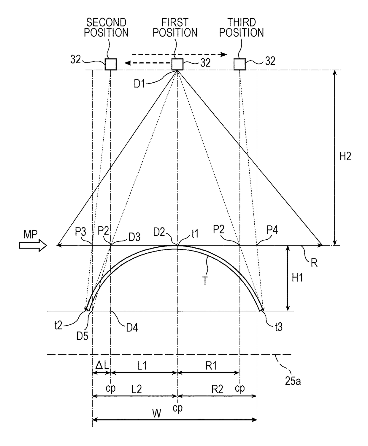
[0215]FIG. 12 is a flowchart illustrating a flow of a process for acquiring nail information and a nail image according to Modified Example 1.

[0216]FIG. 13 is an explanatory diagram schematically illustrating the operation of the imaging unit 30 during the process of acquiring nail information and a nail image for explaining the process.

[0217]First, the imaging control unit 511 controls the motor 43 that is a moving unit to move the imaging unit 30 so that the reference point CP of the imaging range R of the camera 32 overlaps with the peak t1 of the nail T (step S131).

[0218]This positioning corresponds to a first positioning according to the present invention, and the position of the camera 32 resulting from the positioning is a first position in FIG. 13. This position corresponds to a reference of the coordinates.

[0219]Subsequently, the imaging control unit 511 controls the camera 32 at the first position to acquire an image (first image) of a nail that i...

modified example 2

[0245][Modified Example 2]

[0246]FIG. 14 is a flowchart illustrating a flow of a process for acquiring nail information and a nail image according to Modified Example 2.

[0247]FIG. 15 is an explanatory diagram schematically illustrating the operation of the imaging unit 30 during the process of acquiring nail information and a nail image for explaining the process.

[0248]First, the imaging control unit 511 controls the motor 43 that is a moving unit to move the imaging unit 30 in such a manner as to scan the entire movable range (step S231).

[0249]In this process, the imaging control unit 511 moves the imaging unit 30 while continuing imaging operation with the camera 32.

[0250]The imaging control unit 511 then performs image processing on a nail image (second image) acquired by imaging at each predetermined timing and recognizes the right edge of the nail in the nail image.

[0251]The imaging control unit 511 then determines whether or not the right edge of the nail is present in the nail...


PUM


Abstract

A nail information detection device includes: a placement surface on which a finger having a nail is placed; an imaging unit which images the nail from one direction and acquires a image data; a moving unit which moves the imaging unit while keeping a distance between a measurement plane which is in contact with a peak position of the nail and parallel to the placement surface and the imaging unit constant; and a control unit configured to detect nail information including a first edge position and a second edge position on a shape of the nail.The control unit aligns a reference point of an imaging range of the imaging unit at the peak position and detects a position on the measurement plane of the nail edge based on the image data as the first edge position; and aligns the reference point at the first edge position and detects a position on the measurement plane of the nail edge based on the image data as the second edge position.

Description

CROSS-REFERENCE TO RELATED APPLICATIONS[0001]This application corresponds to Japanese Patent Application No. 2014-192125 filed on Sep. 22, 2014.BACKGROUND OF THE INVENTION[0002]1. Field of the Invention[0003]The present invention relates to a nail information detection device, a drawing apparatus, and a nail information detection method.[0004]2. Description of the Related Art[0005]In related art, painting devices for printing nail designs on fingernails and toenails are known. Such a painting device is disclosed in JP 2003-534083 A, for example. Use of such a painting device allows for easily enjoying nail designs without use of nail salons or the like.[0006]Such a painting device is configured to image a nail with a camera before painting, detect a nail region from an obtained image, and paint an image on the detected nail region.[0007]The painting device as described above is configured to image a nail only in one direction with a single camera. Note that nails have shapes curving...

Claims


Application Information

Patent Timeline
Patent Type & Authority Patents(United States)
IPC IPC(8): H04N5/225G06T7/55H04N5/232A45D29/00
CPCH04N5/225A45D29/00G06T7/55H04N5/23229A45D2029/005H04N23/80H04N23/00
Inventor YAMASAKI, SHUICHI
Owner CASIO COMPUTER CO LTD
Learn More