Mechanically disengaging overrunning clutch

a clutch and mechanical technology, applied in the field of one-way clutches, can solve the problems of ratcheting of the actuating plate, actuation provided by an electric motor, etc., and achieve the effects of reducing relative speed, avoiding abrupt or shock impact, and facilitating engagement and disengagemen

Active Publication Date: 2017-07-18
BATES JULIAN
View PDF6 Cites 0 Cited by
  • Summary
  • Abstract
  • Description
  • Claims
  • Application Information

AI Technical Summary

Benefits of technology

[0006]The advantage of not having a connection, under certain operating conditions, between the drive and driven members provides improvements in energy efficiency and wear of the clutch. In addition, actuation is not provided by an electric motor that converts electrical energy into mechanical motion. Rather, actuation is made possible by cam tracks in an outermost cam plate connected to a drive or driven member, which contains cam track grooves for the actuation plate's track followers. The track followers slide the actuation plate into a position in the cam tracks that can hold or keep the clutch in its “open” or decoupled position during rotation.
[0008]In one embodiment, the clutch assembly uses helical teeth to couple the drive and driven members and helical teeth are on the inner race of an actuating plate and on the outer race of a counter plate, which is connected to an opposite drive. Therefore, if the design calls for the cam plate to be connected to the drive, then the counter plate is connected to the driven member. The helical teeth are mutually spaced apart on each of the respective races so that the teeth equally hold torque during backspin, and during overrunning ratcheting is allowed, which can lead to full disengagement under certain operating conditions. The helical teeth allow for engagement and disengagement to be smooth, avoiding an abrupt or shock impact. This assembly also has friction material adhered to the actuating plate's flange, which provides impact absorption and friction to help reduce relative speed between the drives during backlash.
[0009]In another embodiment, the clutch assembly uses jaw teeth to couple the drive and driven members have teeth that are similar to jaw clutches with sawtooth-like teeth. However, the teeth are angled “forward” along the circumference of the plate's diameter, which in turn facilitates engagement and disengagement initiated by rotation between the actuating and counter plates. Therefore, the jaw teeth produce similar engagement and disengagement characteristics that are employed by the assembly utilizing helical teeth. The usually sharp tips of the sawtooth-like jaw teeth are rounded off. The counter plate's jaw teeth geometrically adjoin to the actuation plate's teeth geometry. However, when absorption or shock padding is adhered to the counter plate's teeth surface the plate's tooth geometry is changed to compensate for the padding. This padding is intended to prevent shock impact during relatively high engagement speeds or during high impact backspin or backlash and is not intended to provide otherwise additional friction, but is a surface that facilitates engagement and disengagement between the teeth while increasing durability in higher torque capacity applications. The teeth on the counter plate can be made to fit the teeth of the actuating plate without the use of padding, therefore losing the benefits of an impact absorbing material, but benefiting from design simplicity. Overrunning characteristics are similar regardless of assembly and may occur if the relative rotational speed difference between the drive and driven members is in the same direction or when one of the plates connected to either the drive or driven members is stationary.

Problems solved by technology

In addition, actuation is not provided by an electric motor that converts electrical energy into mechanical motion.
When the drive connected to the cam plate overruns the drive connected to the counter plate, the actuating plate's teeth (helical or jaw) slide over the counter plate's adjoining teeth causing ratcheting of the actuating plate.

Method used


Image

  • Mechanically disengaging overrunning clutch
  • Mechanically disengaging overrunning clutch
  • Mechanically disengaging overrunning clutch

Examples


Embodiment Construction

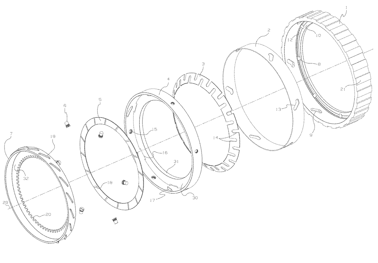
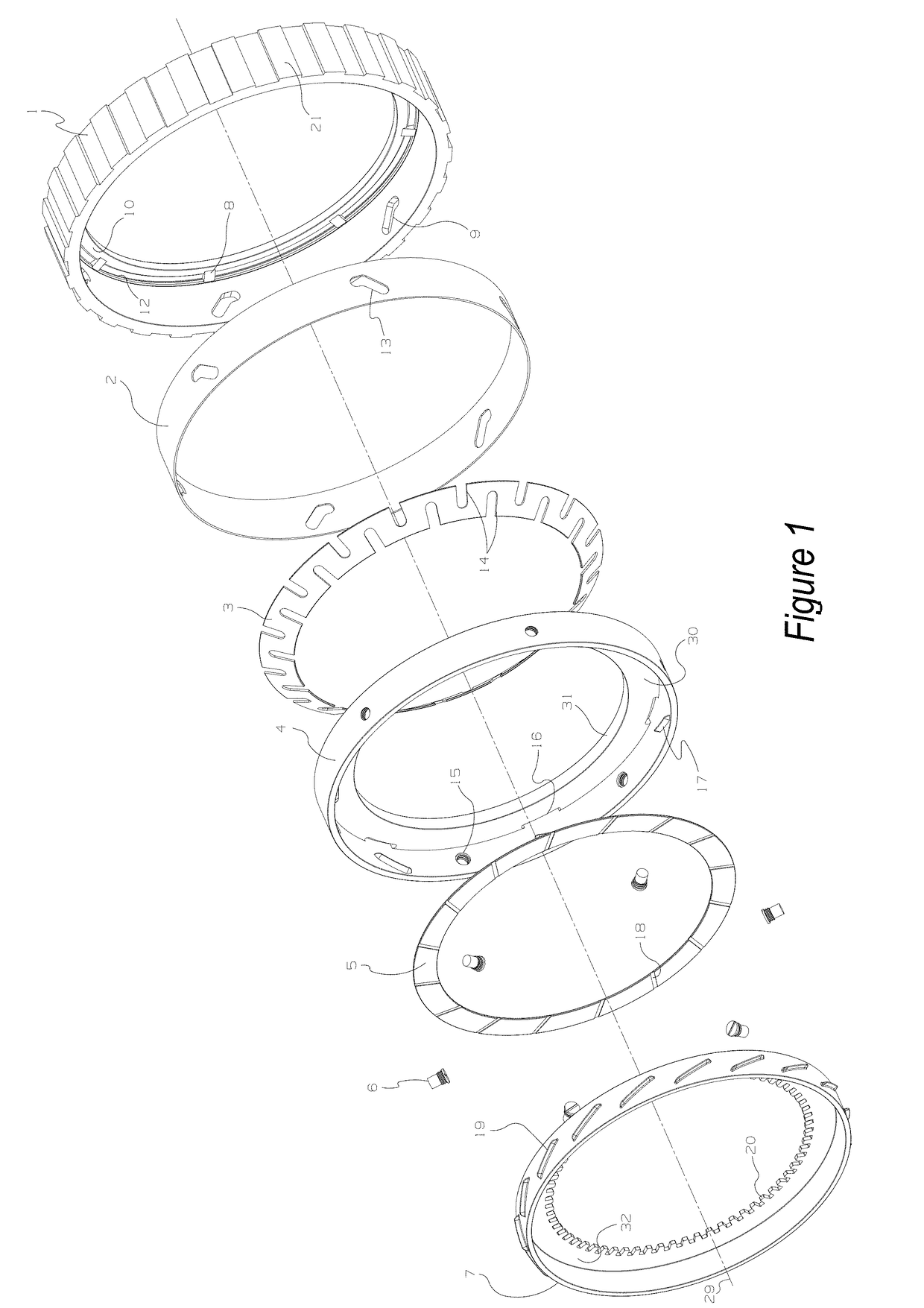
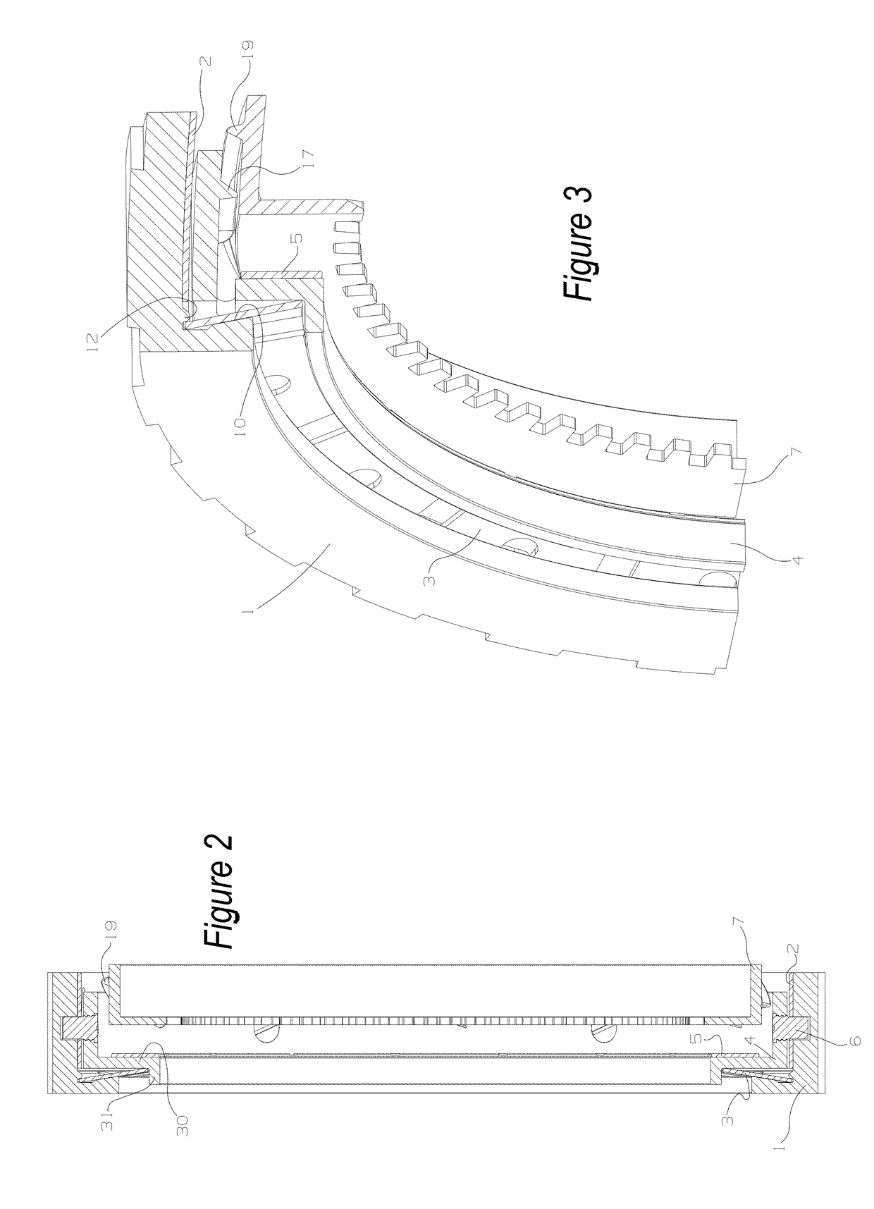
[0025]A one-way clutch for a motor vehicle is provided. The one-way clutch includes a cam plate with outer splines and a counter plate with inner splines. The one-way clutch also includes an actuation plate between the cam plate and the counter plate, the actuation plate having a predetermined and limited amount of sliding engagement with the cam plate. An engagement mechanism that is operable to provide selective engagement between the actuation plate and the counter plate can also be present. Finally, a biasing member between the cam plate and the counter plate is present and the biasing member is operable to expand and contract in a direction that is parallel to a central axis of the cam plate. The biasing member also moves the actuation plate along the central axis between an overrun position with the counter plate and a disengaged position with the counter plate.

[0026]The cam plate can have a side wall with an inner race and the side wall can have a plurality of cam track groov...


PUM


Abstract

A one way overrunning clutch capable of fully disconnecting a drive and driven members during overrunning by utilizing helical teeth or utilizing jaw teeth. Both assembly types provide a drive connection in one rotational direction and allow for overrunning in the opposite rotational direction. Both helical and jaw tooth coupling systems contain a spring loaded actuating plate allowing it to move along either assembly's common axis, enabling components connected to the drive or driven to be completely unconnected when overrunning occurs under certain operating conditions.

Description

CROSS-REFERENCE TO RELATED APPLICATIONS[0001]The instant application claims priority to U.S. Provisional Patent Application No. 62 / 041,131 filed on Aug. 24, 2014, which is incorporated in its entirety herein by reference.FIELD OF THE INVENTION[0002]The present application is directed to a one-way clutch, and in particular to a one-way clutch having a fully disconnected drive and driven members during overrunning through the use of helical teeth or jaw teeth.BACKGROUND OF THE INVENTION[0003]One-way clutches in rotary power transmission systems that can be used as safety devices and / or shift components are known. Such one-way clutches are commonly used in the powertrain or driveline of automotive vehicles. However, heretofore known one-way clutches exhibit ratcheting when the clutch is in an overrun configuration in which gear teeth slide mechanically over each other. Such ratcheting involves frictional losses due to the mechanical sliding between gear teeth and thus less than desired...

Claims


Application Information

Patent Timeline
Patent Type & Authority Patents(United States)
IPC IPC(8): F16D41/18
CPCF16D41/185
Inventor BATES, JULIAN
Owner BATES JULIAN
Why Eureka
Try Eureka