
Tubular skylight diffuser element and method of manufacturing a diffuser element

a technology of diffuser elements and tubular skylights, which is applied in the direction of skylights/domes, roofs, buildings, etc., can solve the problems of unfavorable occupant comfort, unfavorable occupant comfort, and inability to meet the needs of occupant comfort, so as to achieve better insulating properties, reduce the u-value of accessories, and improve the effect of occupant comfor

Active Publication Date: 2017-07-11
VKR HLDG AS
View PDF20 Cites 1 Cited by
  • Summary
  • Abstract
  • Description
  • Claims
  • Application Information

AI Technical Summary

Benefits of technology

[0030]In accordance with yet still further aspects of other embodiments of the present technology, the light path zone y be transparent. With this embodiment it may be achieved to increase further the amount of natural light that may be provided to the room. The light that enters the room through the light path zone may be unfiltered. When the sun is shining outside, the light rays that enter through the light path zone will appear as unfiltered sunlight. Moreover, the effect of the glowing side of the diffuser may be more pronounced. With the method according to the invention, the translucent effect in the bottom portion may be achieved in a way that would require no extra steps as soon as the mold may be finished.
[0090]It may be herewith achieved that the U-value of the accessory may be decreased dependent on the materials used. The overall U-value of the tubular skylight will benefit from this alternative. The U-value is a measure of heat transmission through a building part, with lower numbers indicating better insulating properties. The U-value of the accessory may be further decreased by adding additional disc-shaped elements. The first disc-shaped element and the additional disc-shaped elements may be provided in identical materials in one embodiment or in different materials in other embodiments.

Problems solved by technology

When the temperature difference between the outside and the inside of the building is sufficiently great, heat flowing through the skylight, in either direction, may cause discomfort to the occupants of the building.
The temperature difference may undesirably require additional heating or cooling inside the building to maintain comfort for the building occupants.

Method used


Image

  • Tubular skylight diffuser element and method of manufacturing a diffuser element
  • Tubular skylight diffuser element and method of manufacturing a diffuser element
  • Tubular skylight diffuser element and method of manufacturing a diffuser element

Examples


second embodiment

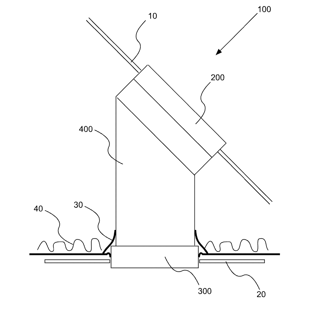
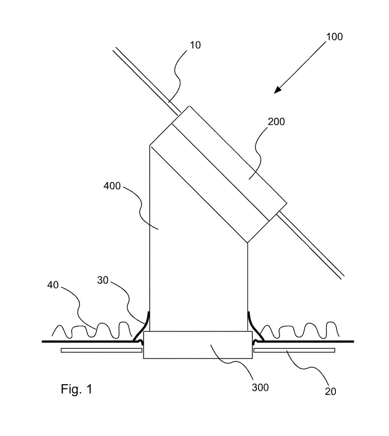
[0150]FIG. 13 illustrates detail A of FIG. 10 in the invention in which the first and second condensate collectors 360′, 360″ comprise a drain 380 for removing condensate from the condensate collectors 360′, 360″. The drain 380 comprises a drain pipe 384. The drain pipe 384 extends into the groove 364 at one end and through the vapor barrier 30 at the other end. The drain pipe 384 has a drain inlet 382 at the lower end 368 of the groove 364 and a drain outlet 386 on outside the vapor barrier 30. The drain outlet 386 is in corn communication with a discharge. In the embodiment shown, the condensate is discharged through evaporation to the surrounding. In alternative embodiments the discharge is a pump or a heated evaporator. As the first and second condensate collectors 360′, 360″ are fluidly connected the drain pipe 384 will remove condensate from both condensate collectors 360′, 360″. In alternative embodiments where the first and second condensate collectors 360′, 360″ are separat...

third embodiment

[0153]FIG. 14 illustrates detail A of FIG. 10 in the invention. In this embodiment, the tube 400 terminates above the first and second condensate collector 360′, 360″. The first and second inlets 362′, 362″ are the same.

[0154]FIG. 15 illustrates a schematic view of the accessory 500 in an embodiment installed in the ceiling mounted element 300 or the tube 400.

[0155]The holding means 540 has a resilient element 542. When inserted into the ceiling mounted element 300 or the tube 400, the resilient element 542 is deformed and therefore applies a normal force on the inner surface of the bore of the ceiling mounted element 300 or the tube 400. The accessory 540 is thereby retained via friction between the resilient element 542 and the ceiling mounted element 300 or the tube 400 respectively.

[0156]FIG. 16 illustrates a schematic view of the accessory 500 in an embodiment having removal means 560 in the form of handles.

[0157]When it is required to remove the accessory 500, a user can grip ...


PUM


Abstract

A tubular skylight is provided, comprising a roof mounted element for collecting exterior light, a ceiling mounted element, and a tube connecting the roof mounted element and the ceiling mounted element. The skylight includes a diffuser element mounted in the ceiling mounted element for distributing the exterior light in a room. The diffuser element includes a first diffuser pane having a translucent bottom portion and a sidewall portion with a translucent light path zone. The tubular skylight has means for affecting the luminance of the light exiting the diffuser such that the luminance of light exiting through the light path zone has a different luminance than light exiting through the bottom portion. The ceiling mounted element and the diffuser element provide a light passage from the light path zone to the room by a free space adjacent the light path zone.

Description

CROSS-REFERENCE TO RELATED APPLICATIONS[0001]This application claims priority under 35 U.S.C. §119 to Denmark patent application PA 2014 70746, filed Nov. 28, 2014, and to Denmark patent application PA 2014 70747, filed Nov. 28, 2014, the disclosures of both of which are incorporated herein by reference.STATEMENT REGARDING FEDERALLY SPONSORED RESEARCH OR DEVELOPMENT[0002]Not applicable.THE NAMES OF THE PARTIES TO A JOINT RESEARCH AGREEMENT[0003]Not applicable.INCORPORATION-BY-REFERENCE OF MATERIALS SUBMITTED ON A COMPACT DISC OR AS A TEXT FILE VIA THE OFFICE ELECTRONIC FILING SYSTEM[0004]Not applicable.STATEMENT REGARDING PRIOR DISCLOSURES BY THE INVENTOR OR A JOINT INVENTOR[0005]Not applicable.BACKGROUND OF THE INVENTION[0006]Field of the Invention[0007]The current invention relates to a tubular skylight comprising a roof-mounted element for collecting exterior light, a ceiling mounted element, a tube connecting the roof mounted element and the ceiling mounted element and a diffuse...

Claims


Application Information

Patent Timeline
Patent Type & Authority Patents(United States)
IPC IPC(8): E04D13/03G02B5/02
CPCE04D13/033G02B5/0278E04D2013/0345
Inventor KRISTENSEN, KRISTIAN NITZSCH
Owner VKR HLDG AS
Learn More