
Non-aqueous electrolyte secondary battery

a secondary battery and electrolyte technology, applied in the field of non-aqueous electrolyte secondary batteries, can solve the problems of deteriorating battery performance, difficult to deal with the aforementioned phenomenon, and battery voltage drop, so as to improve thermal stability and mechanical strength (shape stability), reduce battery resistance, and improve the effect of mechanical strength

Active Publication Date: 2017-07-04
TOYOTA JIDOSHA KK
View PDF4 Cites 0 Cited by
  • Summary
  • Abstract
  • Description
  • Claims
  • Application Information

AI Technical Summary

Benefits of technology

[0008]The present invention provides a non-aqueous electrolyte secondary battery in which the internal short circuit caused by the invading foreign matter is less likely to occur and which is excellent in the reliability and endurance.
[0019]As described above, the aforementioned non-aqueous electrolyte secondary battery (e.g., a lithium ion secondary battery) may well maintain battery performance and exert a high reliability even if a foreign matter enters. For example, the input / output density is high, and the endurance is excellent. Therefore, by taking advantage of the characteristics, such a battery can be well used as, e.g., a power source (driving power supply) of a vehicle.

Problems solved by technology

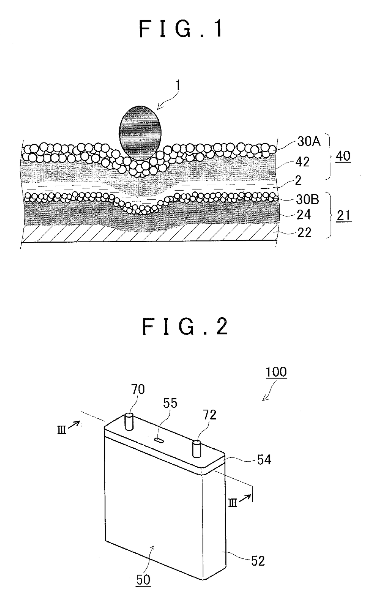
In a case that the foreign matter is present in the vicinity of a surface of the electrode, for example, the separator may be broken (ruptured) and small internal short circuit may occur in the battery, thereby deteriorating battery performance (e.g., a decrease in battery voltage).
According to study of the present inventor, in the technology disclosed in International Publication No. 2008 / 149895, in particular when the foreign matter has a sharp (pointed) tip, it may be difficult to deal with the aforementioned phenomenon.
Further, it was determined that the separator may be broken by such a stress, causing occurrence of the internal short circuit.

Method used


Image

  • Non-aqueous electrolyte secondary battery
  • Non-aqueous electrolyte secondary battery
  • Non-aqueous electrolyte secondary battery

Examples


Embodiment Construction

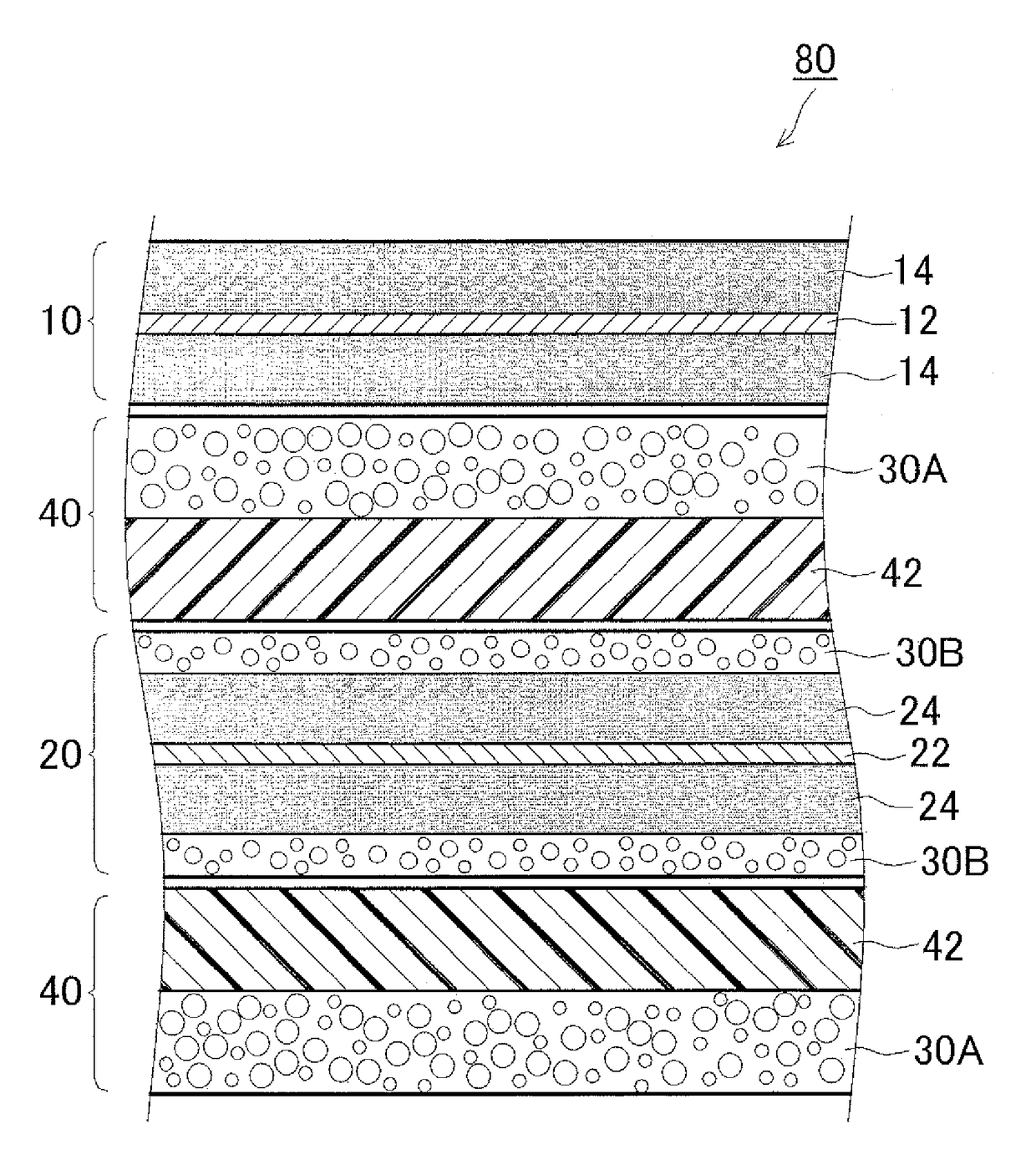
[0028]Hereinafter, preferable embodiments of the present invention will be described with reference to the drawings. In the following accompanying drawings, the like members and regions that play the same roles are denoted with like numerals. Further, a dimensional relationship (length, width, thickness and the like) in each of drawings does not reflect an actual dimensional relationship. Moreover, items that are necessary for carrying out the present invention other than items particularly referred to in this Specification may be grasped as design matters of a person skilled in the art based on the related art in the concerned field. The present invention may be carried out based on contents disclosed in this Specification and common technical knowledge in the concerned field.

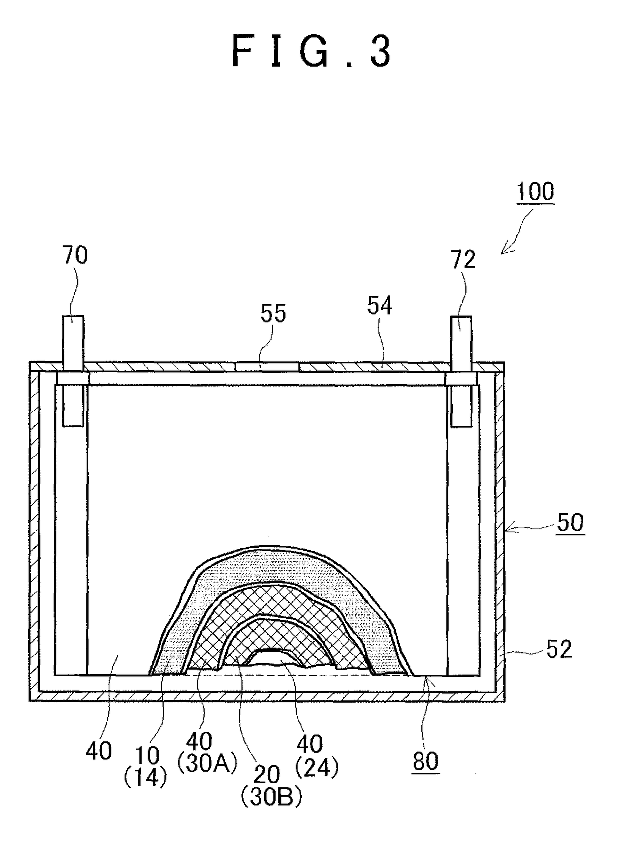
[0029]Although not particularly intended to limit, hereinafter, as a schematic structure of a non-aqueous electrolyte secondary battery according to one embodiment of the present invention, a non-aqueous elect...


PUM

PropertyMeasurementUnit
thicknessaaaaaaaaaa
thicknessaaaaaaaaaa
particle diameteraaaaaaaaaa

Abstract

The present invention provides a non-aqueous electrolyte secondary battery having an electrode body formed by stacking a positive electrode, a separator and a negative electrode and a non-aqueous electrolyte. The separator has a separator substrate made and a first porous heat resistance layer formed on a surface of the substrate on a side facing the positive electrode. A surface of the negative electrode on a side facing the separator is formed by a second porous heat resistance layer. The first and second porous heat resistance layers satisfy: (1) an average thickness of the first porous heat resistance layer is greater than that of the second porous heat resistance layer; (2) an average particle diameter of an inorganic filler contained in the first porous heat resistance layer is greater than that of an inorganic filler contained in the second porous heat resistance layer.

Description

INCORPORATION BY REFERENCE[0001]The disclosure of Japanese Patent Application No. 2013-209306 filed on Oct. 4, 2013 including the specification, drawings and abstract is incorporated herein by reference in its entirety.BACKGROUND OF THE INVENTION[0002]1. Field of the Invention[0003]The present invention relates to a non-aqueous electrolyte secondary battery. Specifically, the present invention relates to a non-aqueous electrolyte secondary battery provided with a porous heat resistance layer on surfaces of a separator and a negative electrode.[0004]2. Description of Related Art[0005]Non-aqueous electrolyte secondary batteries such as lithium ion secondary batteries and nickel hydrogen batteries are recently used as so-called portable power sources for personal computers and portable terminals and vehicle driving power sources. In particular, lithium ion secondary batteries that are lightweight and can afford high energy density are preferably used as high output driving power source...

Claims


Application Information

Patent Timeline
Patent Type & Authority Patents(United States)
IPC IPC(8): H01M2/16H01M2/34H01M4/36H01M10/0525H01M50/431H01M50/451H01M50/457H01M50/491
CPCH01M2/1686H01M2/1613H01M2/1646H01M2/1673H01M2/347H01M2/348H01M4/366H01M10/0525H01M2200/10H01M50/431H01M50/44H01M50/46H01M50/579H01M50/581H01M50/451H01M50/491H01M50/457Y02E60/10Y02P70/50
Inventor IWASE, KOSUKE
Owner TOYOTA JIDOSHA KK
Learn More