
Air cavity LED backlight unit

a backlight unit and air cavity technology, applied in mechanical devices, lighting and heating devices, instruments, etc., can solve the problems of insufficient spatial uniformity and illuminance of leds, inability to accurately display images, and large acrylic sheets being expensive and heavy. , to achieve the effect of sufficient spatial uniformity and illuminance, accurate display of images

Active Publication Date: 2017-06-27
SEOUL SEMICONDUCTOR
View PDF20 Cites 0 Cited by
  • Summary
  • Abstract
  • Description
  • Claims
  • Application Information

AI Technical Summary

Benefits of technology

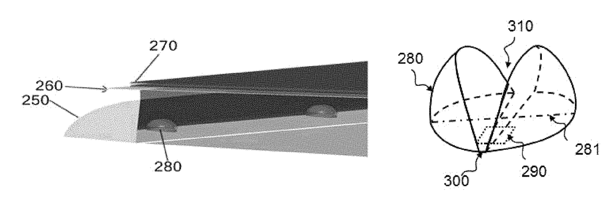
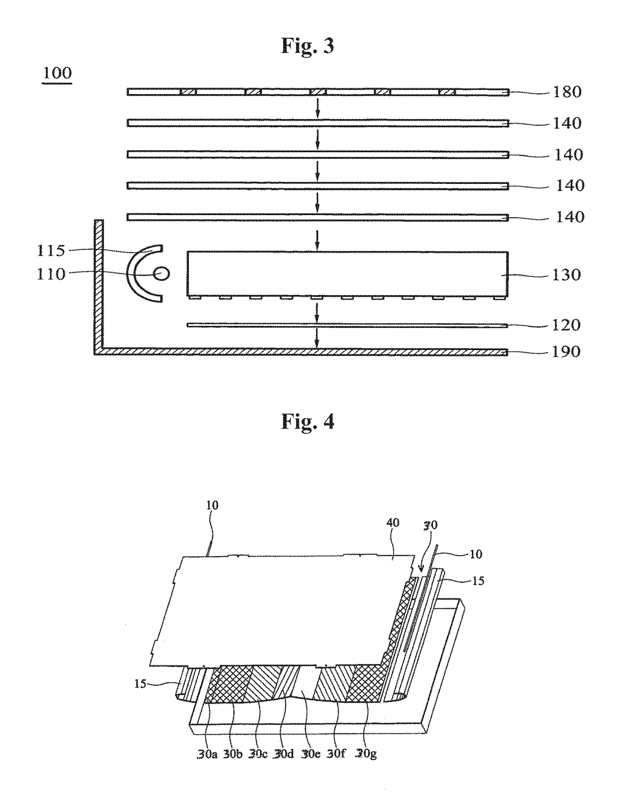
[0013]An exemplary embodiment of the present invention discloses a transmissive display such as a liquid crystal display (LCD) that is illuminated by a backlight assembly. The backlight assembly includes an array of LEDs, that has its light transported via a reflective baffle such that it illuminates a hollow-cavity light chamber. The transmissive display is positioned adjacent the light chamber so that the light exiting the light chamber and passing through an optical conditioning stack of filters then illuminates the transmissive display. The backlight assembly includes a bottom floor specular reflector or a combination of a specular and diffuse bottom floor reflectors and an array of baffled localized optical lenses positioned over each LED source to ensure that the light leaving the optical cavity through the optical conditioning film stack will achieve sufficient spatial uniformity and illuminace so that the LCD can accurately display the images from its various pixel elements.
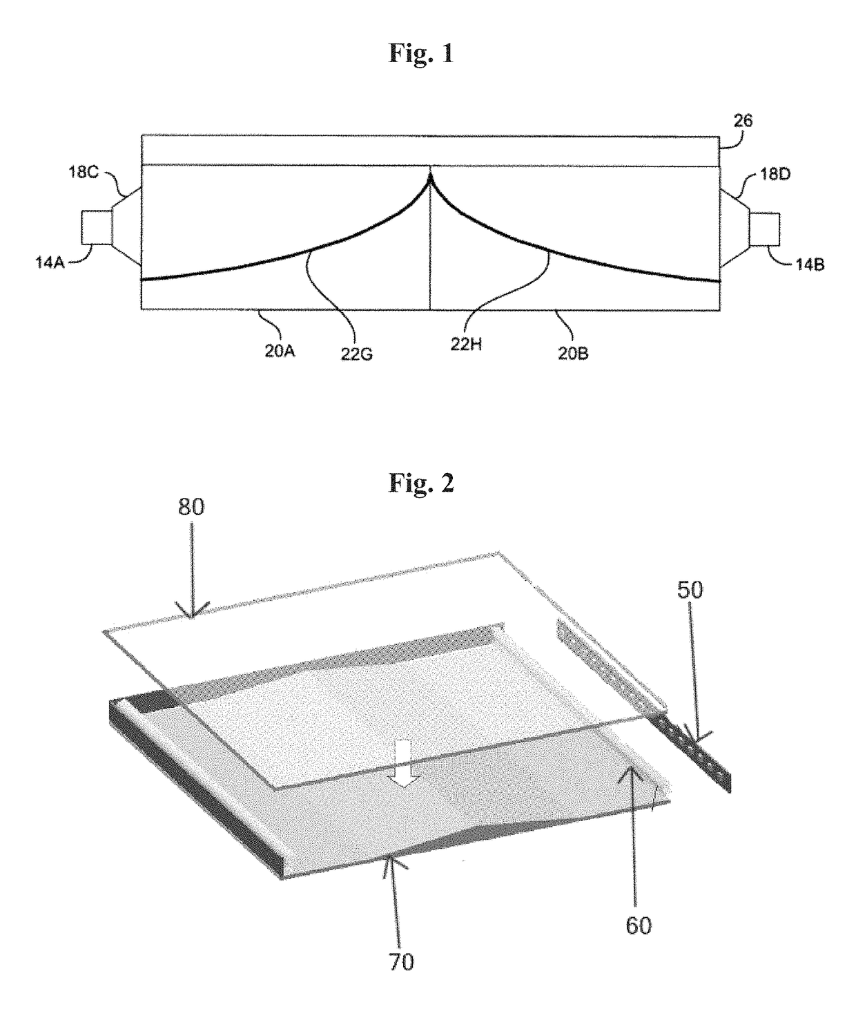
[0015]An exemplary embodiment of the present invention also discloses a low-profile 10 mm or less thick LED BLU that uses a specular and diffuse bottom reflector having a reflectivity of 98+% in combination, which inject light from two sides of the BLU into a hollow air-cavity, together with local optical elements placed over the LEDs to achieve excellent spatial uniformity and illuminance at the transmissive LCD display.
[0016]An exemplary embodiment of the present invention also discloses a low profile LED BLU that injects light from an array of LEDs from a single non-symmetrical side of the BLU and uses a specular and diffuse bottom reflector having a reflectivity of 98+% in combination to transport the light to the transmissive LCD display, and uses local optical elements to achieve excellent spatial uniformity at the LCD display in both the longitudinal as well as the lateral directions.

Problems solved by technology

However, the large acrylic sheets may be expensive and weigh too much.
However, as the thickness of the backlight unit decreases from 25 mm down to the 11-12 mm range, the refractive optical principles upon which these lenses are based may cease to yield acceptable uniformity.
However, at the time this patent issued, LEDs were not very efficient or powerful, but subsequently white LEDs have gone from an efficacy of about 5 lumens / Watt to more than 200 lumens / Watt.
Thus, the baffling technology disclosed in U.S. Pat. No. 6,007,209 may provide a BLU with insufficient uniformity and illuminance value.

Method used


Image

  • Air cavity LED backlight unit
  • Air cavity LED backlight unit
  • Air cavity LED backlight unit

Examples


Embodiment Construction

[0035]The inventive concept is described more fully hereinafter with reference to the accompanying drawings, in which exemplary embodiments of the inventive concept are shown. The inventive concept may, however, be embodied in many different forms and should not be construed as limited to the exemplary embodiments set forth herein. Rather, these exemplary embodiments are provided so that this disclosure is thorough, and will fully convey the scope of the inventive concept to those skilled in the art. In the drawings, the size and relative sizes of layers and regions may be exaggerated for clarity. Like reference numerals in the drawings denote like elements.

[0036]It will be understood that when an element or layer is referred to as being “on” or “connected to” another element or layer, it can be directly on or directly connected to the other element or layer, or intervening elements or layers may be present. In contrast, when an element is referred to as being “directly on” or “dire...


PUM


Abstract

A light-emitting diode (LED) backlight unit includes first and second curved bottom floor reflectors exhibiting mirror image symmetry along a center line extending in a latitudinal direction, first and second sides disposed along a longitudinal direction, the first and second bottom floor reflectors disposed therebetween, first and second back reflectors disposed on distal ends of the first and second bottom floor reflectors, respectively, away from the center line, and LEDs disposed in or adjacent to the first and second back reflectors. A curvature of the first and second bottom floor reflectors respectively reach a maximum near the center line.

Description

CROSS-REFERENCE TO RELATED APPLICATIONS[0001]This application claims priority from and the benefit of U.S. Provisional Application No. 61 / 916,923, filed on Dec. 17, 2013, and U.S. Provisional Application No. 61 / 976,339, filed on Apr. 7, 2014, which are hereby incorporated by reference for all purposes as if fully set forth herein.BACKGROUND[0002]Field[0003]Exemplary embodiments of the present invention relate to a low-profile, thin side-lit, hollow cavity, LED backlight apparatus for LCD TVs, tablets, notebooks computers, and the like.[0004]Discussion of the Background[0005]Light emitting diodes (LEDs) have now become the preferred light sources for the backlight units (BLUs) of liquid crystal display (LCD) panels. As a consequence of their dramatic increase in efficacy, the number of LEDs required to adequately illuminate BLUs has decreased by a factor of 3-4 recently. Also consumer demand for thinner LCD panels in devices such as TVs mean that there may be a need for new optical a...

Claims


Application Information

Patent Timeline
Patent Type & Authority Patents(United States)
IPC IPC(8): F21V7/04F21V5/00F21V3/00F21V8/00
CPCG02B6/0096G02B6/0055
Inventor PELKA, DAVID GMAGARILL, SIMON
Owner SEOUL SEMICONDUCTOR
Learn More