
Implantable lead with flexible paddle electrode array

a flexible, electrode array technology, applied in the field of medical devices and methods, can solve the problems of epidural trauma, reduced flexibility of paddle electrode arrays with staggered electrode arrangement,

Active Publication Date: 2017-06-20
ADVANCED NEUROMODULATION SYST INC
View PDF18 Cites 4 Cited by
  • Summary
  • Abstract
  • Description
  • Claims
  • Application Information

AI Technical Summary

Benefits of technology

The flexible design enhances electrode coverage and stability, reducing trauma during implantation and maintaining effective contact with neural tissue, thereby improving pain management efficacy.

Problems solved by technology

Although a staggered electrode arrangement can provide superior electrode coverage as compared to that of a non-staggered electrode arrangement, a paddle electrode array with a staggered electrode arrangement will have reduced flexibility as compared to a similar paddle electrode array with a non-staggered electrode arrangement.
The more rigid the paddle electrode array, the more likely the paddle electrode array can result in trauma to the epidural space in which it is implanted.

Method used


Image

  • Implantable lead with flexible paddle electrode array
  • Implantable lead with flexible paddle electrode array
  • Implantable lead with flexible paddle electrode array

Examples


Embodiment Construction

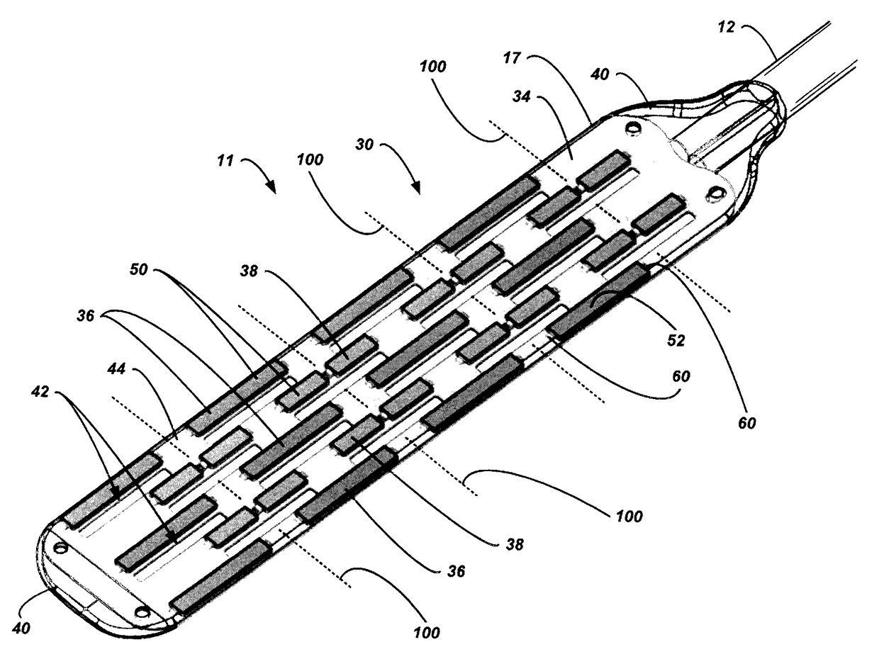
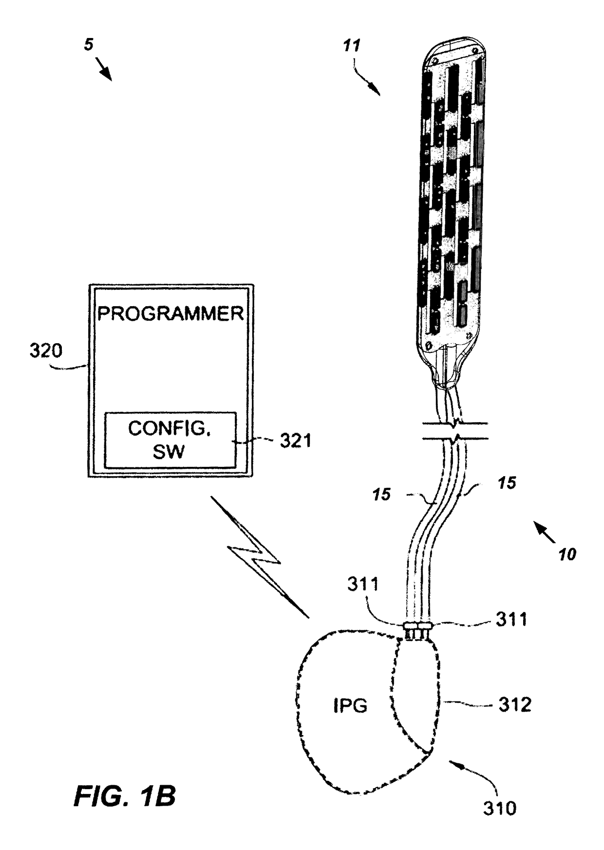
[0034]Neurostimulation systems 5 and methods are disclosed herein. In addition to an implantable pulse generator (IPG) 310, the neurostimulation system 5 also includes an implantable therapy lead 10 that is capable of being coupled to the IPG 310. As discussed in detail below, in one embodiment, the lead 10 includes a flexible paddle electrode array 11 that includes nonflexible electrodes 36 and flexible electrodes 38. Each flexible electrode 38 includes first and second electrode segments 68A, 68B and a living hinge 70 that joins together the electrode segments 68A, 68B to allow the electrode segments 68A, 68B to flex or articulate relative to each other about the living hinge 70, but still remain in solid contact with patient tissue.

[0035]The nonflexible electrodes 36 are grouped into rows of laterally aligned nonflexible electrodes 36 on the flexible paddle electrode array 11. Similarly, the flexible electrodes 38 are grouped into rows of laterally aligned flexible electrodes 38 ...


PUM


Abstract

A neurostimulation system is disclosed herein. The neurostimulation system includes an implantable pulse generator and an implantable therapy lead configured to be electrically coupled to the implantable pulse generator. The implantable therapy lead includes a flexible paddle electrode array with flexible electrodes. Each flexible electrode has a segmented configuration having first and second electrode segments and a flexible bridge or living hinge joining together the first and second electrode segments.

Description

CROSS REFERENCE TO RELATED APPLICATIONS[0001]This is a division of U.S. patent application Ser. No. 14 / 479,066, filed Sep. 5, 2014.FIELD OF THE INVENTION[0002]The present disclosure relates to medical apparatus and methods. More specifically, the present disclosure relates to neurostimulation methods and systems, and more particularly to paddle leadsBACKGROUND OF THE INVENTION[0003]Application of electrical fields to spinal nerve roots, spinal cord, and other nerve bundles for the purpose of chronic pain control has been actively practiced for some time. While a precise understanding of the interaction between applied electrical energy and the neural tissue is not understood, application of an electrical field to spinal nervous tissue (i.e., spinal nerve roots and spinal cord bundles) can effectively mask certain types of pain transmitted from regions of the body associated with the stimulated nerve tissue. Specifically, applying electrical energy to regions of the spinal cord assoc...

Claims


Application Information

Patent Timeline
Patent Type & Authority Patents(United States)
IPC IPC(8): A61N1/05
CPCA61N1/0553Y10T29/49002Y10T29/49117Y10T403/477A61N1/05
Inventor DUBUCLET, JODI TOWNSLEY
Owner ADVANCED NEUROMODULATION SYST INC
Learn More