
Panel structure of power apparatus

a technology of power apparatus and panel structure, which is applied in the direction of electrical apparatus casings/cabinets/drawers, cooling/ventilation/heating modifications, casings/cabinets/drawers details, etc., can solve the problems of easy collapse or deformation of panels, complicated manufacturing procedures, and damage to electronic components, so as to prevent panels from collapsing or deformation, easy to see, and easy to manufacture

Active Publication Date: 2017-06-13
CERNER INNOVATION +1
View PDF15 Cites 8 Cited by
  • Summary
  • Abstract
  • Description
  • Claims
  • Application Information

AI Technical Summary

Benefits of technology

[0006]The primary object of the present invention is to provide a panel structure of a power apparatus. The panel is durable, and the appearance of the panel is pleasing to the eye.
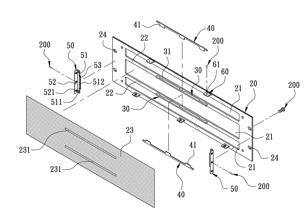
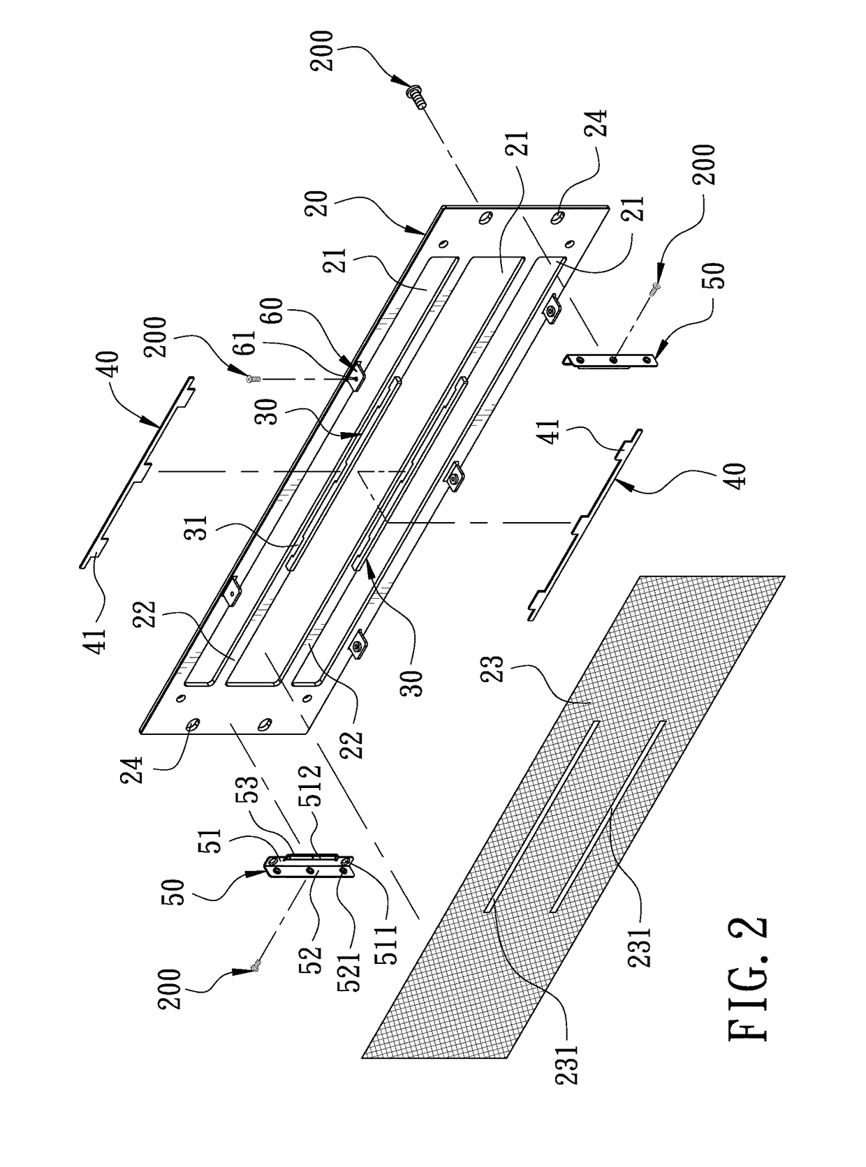
[0008]Accordingly, the connection portion formed between the heat dissipation holes is provided with the reinforcement ribs, preventing the panel from collapsing or deforming. The durability of the panel is increased, and the appearance of the panel is pleasing to the eye.

Problems solved by technology

As a result, the electronic components may be damaged due to the high temperature.
When the ventilating holes of the panel have a certain area, the panel may collapse or deform easily.
Although the ribs can prevent the panel from collapsing or deforming, the procedure to manufacture the panel becomes complicated and the appearance of the panel may be influenced.

Method used


Image

  • Panel structure of power apparatus
  • Panel structure of power apparatus
  • Panel structure of power apparatus

Examples


Embodiment Construction

[0014]Embodiments of the present invention will now be described, by way of example only, with reference to the accompanying drawings.

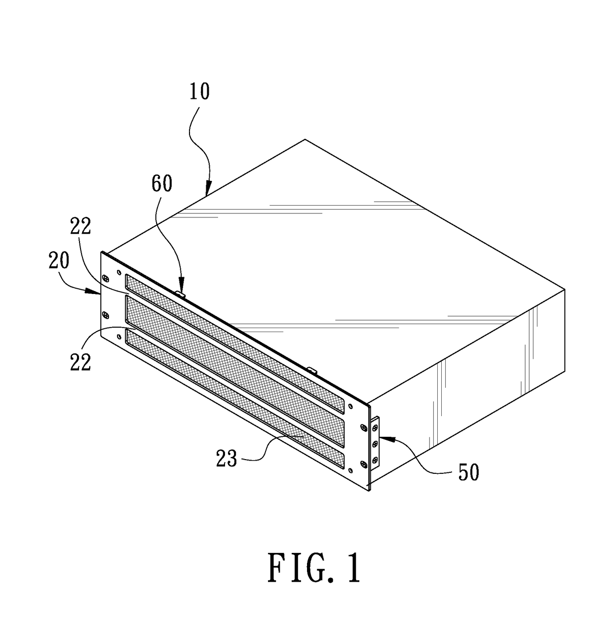
[0015]FIG. 1 is a perspective view showing that a panel according to a preferred embodiment of the present invention is mounted on a case. FIG. 2 is an exploded view of the preferred embodiment of the present invention. The present invention discloses a panel structure of a power apparatus. The power apparatus comprises a case 10. The front of the case 10 is longitudinally provided with a panel 20.

[0016]The panel 20 is transversely formed with at least two parallel heat dissipation holes 21. The heat dissipation holes 21 are adapted for the case 10 to dissipate heat. The panel 20 is formed with a connecting portion 22 between the heat dissipation holes 21. A heat dissipation net 23 is provided on the heat dissipation holes 21. The heat dissipation net 23 is formed with a plurality of openings 231 corresponding to the connecting portion 22. In this pre...


PUM


Abstract

A panel structure of a power apparatus is provided. The power apparatus includes a case. The front of the case is longitudinally provided with a panel. The panel is transversely formed with at least two parallel heat dissipation holes. The panel is formed with a connecting portion between the heat dissipation holes. A heat dissipation net is provided on the heat dissipation holes. The heat dissipation net is formed with a plurality of openings corresponding to the connecting portion. A reinforcement rib is provided on the connecting portion, preventing the panel from collapsing or deforming. The durability of the panel is increased, and the appearance of the panel is pleasing to the eye.

Description

BACKGROUND OF THE INVENTION[0001]1. Field of the Invention[0002]The present invention relates to a panel structure, and more particularly to a panel structure used for a power apparatus.[0003]2. Description of the Prior Art[0004]When a power apparatus runs, the electronic components of the power apparatus will generate heat to bring a high temperate. As a result, the electronic components may be damaged due to the high temperature. In general, the power apparatus is provided with radiating fins, fans or the like therein, alternatively, the panel of the power apparatus is formed with a plurality of ventilating holes and a heat dissipation net is provided on the ventilating holes, enabling the power apparatus to dissipate heat. When the ventilating holes of the panel have a certain area, the panel may collapse or deform easily. Therefore, the ventilating holes are provided with ribs to support the panel so that the panel can achieve the desired effect.[0005]Although the ribs can preve...

Claims


Application Information

Patent Timeline
Patent Type & Authority Patents(United States)
IPC IPC(8): H05K5/03H05K5/00H05K7/20H05K5/02
CPCH05K5/03H05K5/0008H05K7/20127H05K5/0239H05K5/0213
Inventor LIN, MU-CHUN
Owner CERNER INNOVATION
Learn More