
Directional indication structure for threaded body

a directional indication and threaded body technology, applied in the direction of threaded fasteners, fastening devices, and securing devices, can solve the problems of inability to rationally distinguish between a right-handed screw and a left-handed screw based on an external appearance or an outer surface of the internally-threaded body, and achieves easy manufacturing and mass production without increasing costs, aesthetic external appearance, and excellent shaping properties

Active Publication Date: 2017-06-13
NEJILAW
View PDF11 Cites 0 Cited by
  • Summary
  • Abstract
  • Description
  • Claims
  • Application Information

AI Technical Summary

Benefits of technology

The present invention provides a directional indication structure for a threaded body. This structure is easy to manufacture and mass-produce without increasing costs. It can visually and tactilely distinguish between a threaded body with a left-handed screw and a threaded body with a right-handed screw, and can also identify the direction in which the threaded body needs to be rotated to tighten or loosen it. The structure has an excellent shaping property that does not impinge on the inherent properties or durability of the threaded body.

Problems solved by technology

However, it is impossible to screw the externally-threaded body with the right-handed screw with the internally-threaded body with the left-handed screw.
Conversely, it is impossible to screw the externally-threaded body with the left-handed screw with the internally-threaded body with the right-handed screw.
Thus, there may be no difference in terms of an external appearance or an outer surface, and it may be impossible to rationally distinguish between a right-handed screw and a left-handed screw based on an external appearance or an outer surface of the internally-threaded body.

Method used


Image

  • Directional indication structure for threaded body
  • Directional indication structure for threaded body
  • Directional indication structure for threaded body

Examples


Embodiment Construction

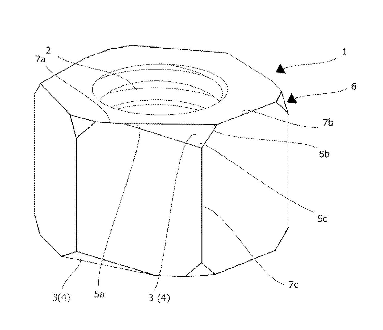
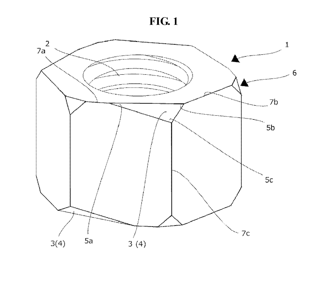
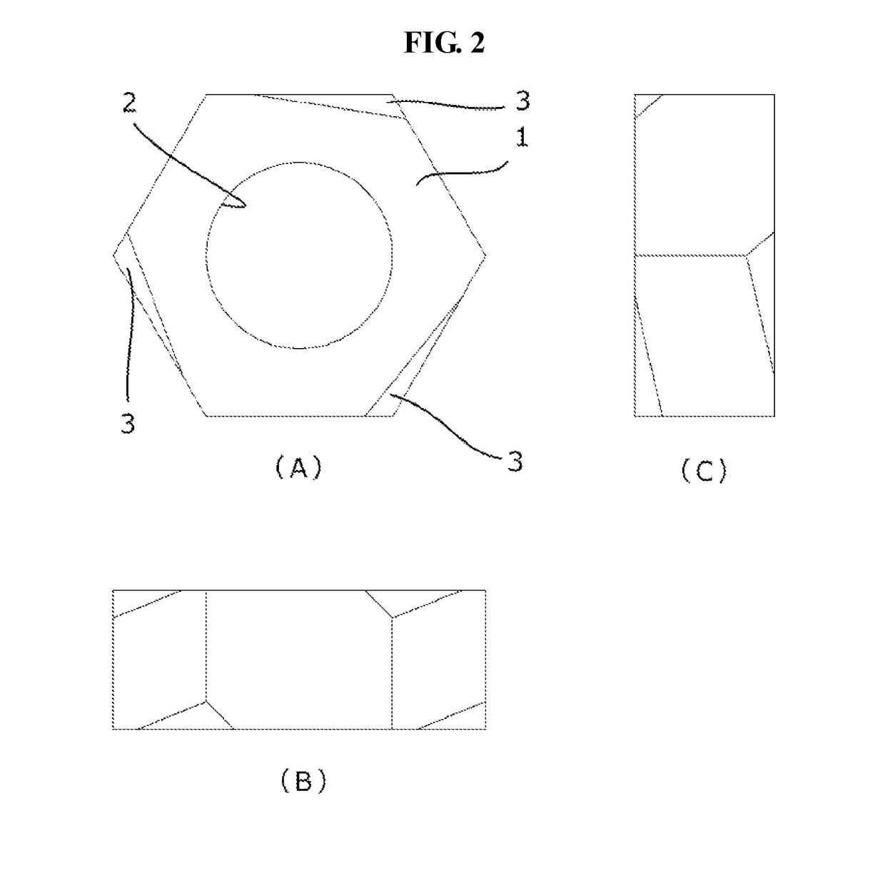
[0022]Hereinafter, embodiments of the present invention will be described in detail with reference to the accompanying drawings (FIGS. 1 and 2). According to embodiments of the present invention, there is provided a directional indication structure for a threaded body that may simultaneously enable visual distinction based on an external appearance, from all directions, and tactile distinction, from an outer surface, between a right-handed screw based threaded body and a left-handed screw based threaded body, and enable identification, from the external appearance and the outer surface, of a direction in which the threaded body is to be rotated to tighten or loosen the threaded body. The structure may be easily manufactured and mass-produced without increasing costs. The structure may have an aesthetic external appearance and an excellent shaping property that may not impinge on the inherent properties or durability of the threaded body.

[0023]The present invention may be applied to ...


PUM


Abstract

[Problem] The present invention aims to provide, without an increase in cost, a directional indication structure for threaded bodies that enables the visual and tactile distinction between left-hand thread and right-hand thread threaded bodies, enables the identification, from the external appearance and the external surface, of which direction a threaded body should be rotated in order to be tightened or loosened, enables mass production and the like, has a good external appearance, and has form properties that do not impinge the properties inherent in the threaded body or the strength, etc. thereof.[Solution] Directional indicators are asymmetrically provided, in association with the direction of rotation of the threads, to the outer surface of a solid body constituting a threaded body, said directional indicators having corner portions which indicate the forward direction in the direction of rotation, and corner portions which indicate the direction in which the threaded body will advance when rotated in the forward direction in the direction of rotation.

Description

CROSS-REFERENCE[0001]The present application is a US National Stage of International Application No. PCT / JP2012 / 070941, filed 19 Aug. 2012, designating the United States, and claiming priority to Japanese Patent Application No. 2011-182279, filed with the Japanese Patent Office on Aug. 24, 2011 and entitled “DIRECTIONAL INDICATION STRUCTURE FOR THREADED BODY”, which is hereby incorporated by reference in its entirety.TECHNICAL FIELD[0002]The present invention relates to a directional indication structure for a threaded body that may enable visual and tactile recognition of a rotation direction and a proceeding direction of a screw for a threaded body, for example, an externally-threaded body, particularly a bolt, and an internally-threaded body, particularly a nut.BACKGROUND ART[0003]In related arts, a screw may include a right-handed screw and a left-handed screw. The right-handed screw may include a thread groove or a thread in a form of a right-handed helix, and the left-handed s...

Claims


Application Information

Patent Timeline
Patent Type & Authority Patents(United States)
IPC IPC(8): F16B37/00F16B1/00F16B33/02
CPCF16B37/00F16B1/0071F16B2033/025F16B2200/95F16B35/06
Inventor HIROSHI, MICHIWAKI
Owner NEJILAW
Learn More