
Antenna

a technology of antenna and antenna head, applied in the field of antenna, can solve the problems of large material cost and processing process cost, and achieve the effect of improving the operating bandwidth of the antenna

Active Publication Date: 2017-06-06
HUAWEI TECH CO LTD
View PDF13 Cites 17 Cited by
  • Summary
  • Abstract
  • Description
  • Claims
  • Application Information

AI Technical Summary

Benefits of technology

The present invention provides an antenna that reduces the size of a normal radiation antenna and improves its bandwidth. This is achieved by using a feeding part and a radiating part that are perpendicular to each other and use dielectric substrates. The substrate integrated waveguide directly radiates energy outwards, resulting in a higher operating bandwidth for the antenna.

Problems solved by technology

However, the normal radiation antenna is formed by superposing twelve layers of metal plates, causing a relatively large volume, and a relatively high material cost and processing process cost.

Method used


Image

  • Antenna
  • Antenna
  • Antenna

Examples


Embodiment Construction

[0022]To make the objectives, technical solutions, and advantages of the present invention clearer, the following further describes the present invention in detail with reference to the accompanying drawings. Apparently, the described embodiments are merely a part rather than all of the embodiments of the present invention. All other embodiments obtained by a person of ordinary skill in the art based on the embodiments of the present invention without creative efforts shall fall within the protection scope of the present invention.

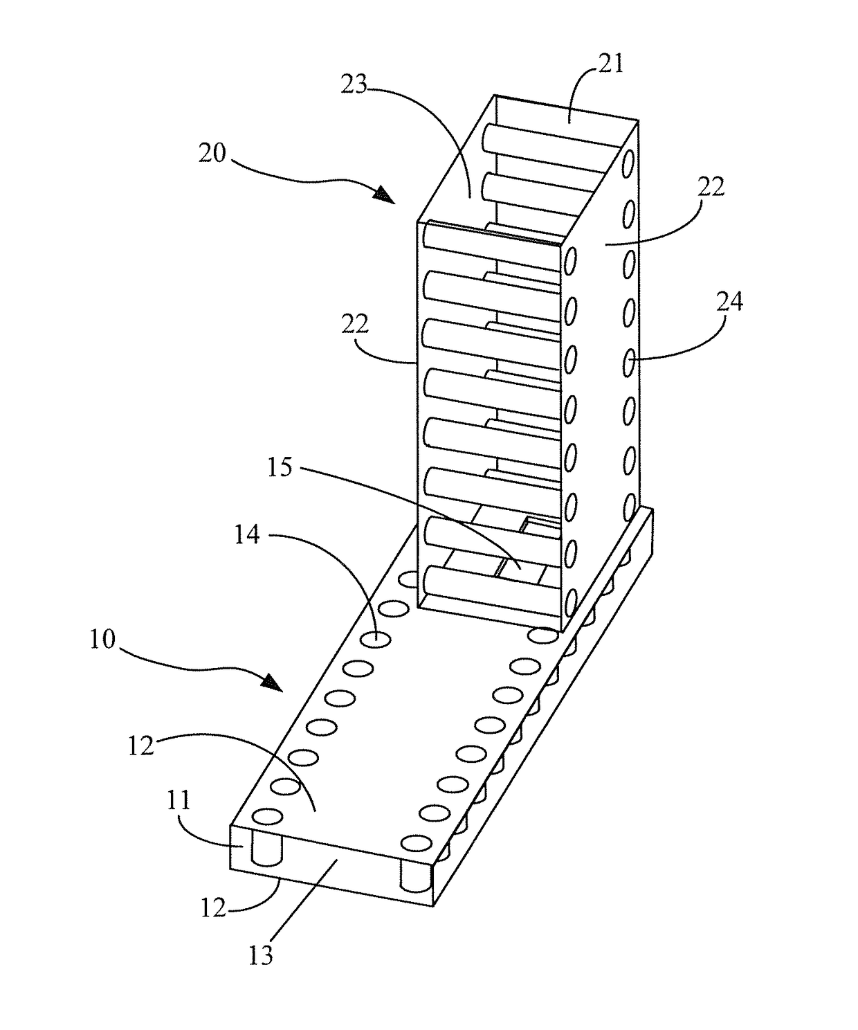
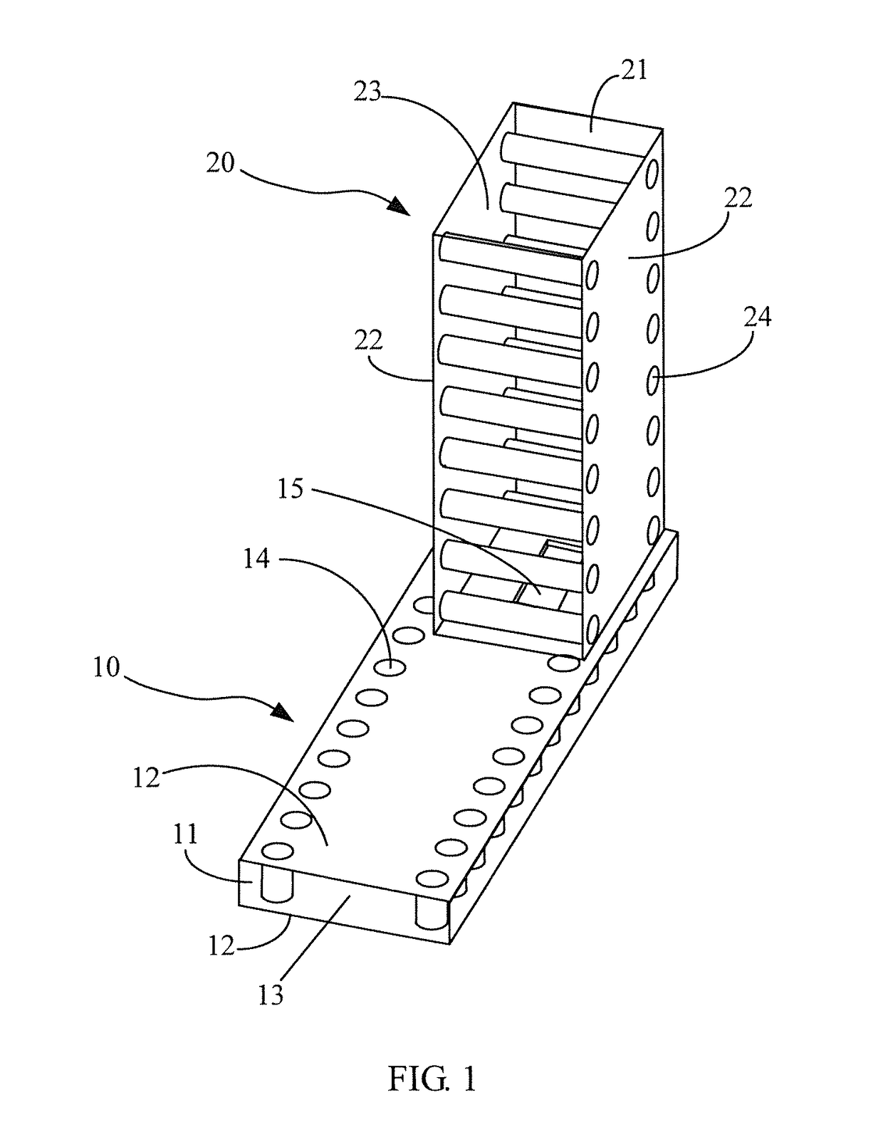
[0023]FIG. 1 is a schematic structural diagram of an antenna according to an embodiment of the present invention. In order to show an internal structure of the antenna more clearly, transparency processing is performed on a first dielectric substrate and a second dielectric substrate in FIG. 1. In addition, because metal layers on a surface of the first dielectric substrate and a surface of the second dielectric substrate are relatively thin, thicknesses o...


PUM


Abstract

The present invention relates to an antenna, which includes a feeding part and a radiating part. By using the feeding part and the radiating part that are perpendicular to each other and use dielectric substrates, not only a volume of a normal radiation antenna is reduced, but also a substrate integrated waveguide directly radiates energy outwards, thereby improving operating bandwidth of the antenna.

Description

CROSS-REFERENCE TO RELATED APPLICATIONS[0001]This application is a continuation of International Application No. PCT / CN2013 / 080544, filed on Jul. 31, 2013, which is hereby incorporated by reference in its entirety.TECHNICAL FIELD[0002]The present invention relates to wireless communications technologies, and in particular, to an antenna.BACKGROUND[0003]With the development of wireless communications technologies, use of a substrate integrated waveguide appears to implement a millimeter wave antenna. The substrate integrated waveguide is a new type of a planar transmission line, and not only has good performance similar to performance of a metallic waveguide, and but also has a structural feature similar to a structural feature of a traditional planar transmission line. Therefore, the substrate integrated waveguide is quite suitable for design of a millimeter wave antenna.[0004]A millimeter wave antenna includes an end-fire antenna and a normal radiation antenna. Compared with the en...

Claims


Application Information

Patent Timeline
Patent Type & Authority Patents(United States)
IPC IPC(8): H01Q13/06H01P5/02H01Q1/38H01P1/02
CPCH01Q13/06H01P5/024H01Q1/38H01P1/025H01P1/027
Inventor CHENG, YUJIANCHEN, YI
Owner HUAWEI TECH CO LTD
Learn More