
Method for message transfer in computer storage system

a message transfer and computer storage technology, applied in the field of data storage systems, can solve the problem of increasing the data transfer bandwidth of the system, and achieve the effect of facilitating data transfer

Inactive Publication Date: 2006-07-04
EMC IP HLDG CO LLC
View PDF80 Cites 12 Cited by
  • Summary
  • Abstract
  • Description
  • Claims
  • Application Information

AI Technical Summary

Benefits of technology

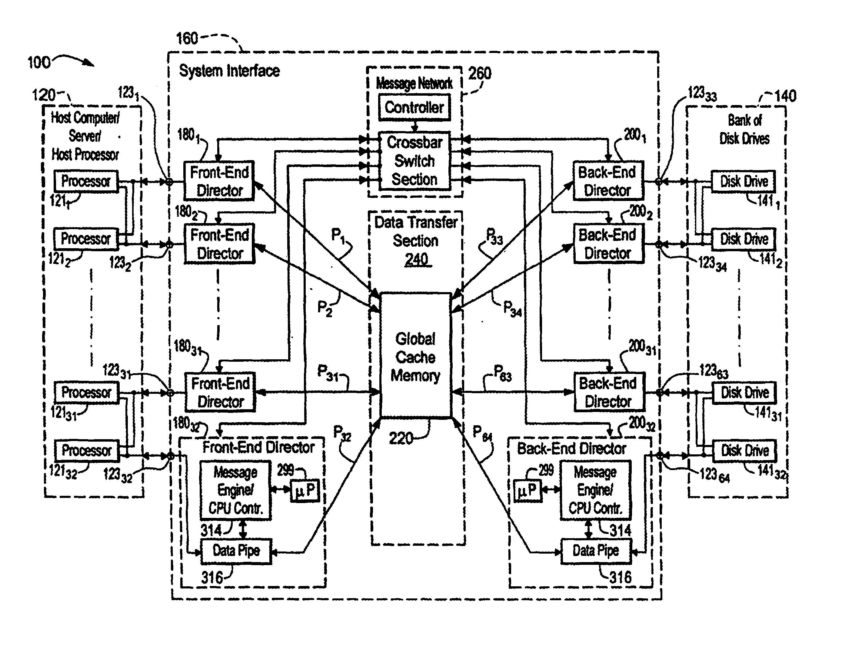
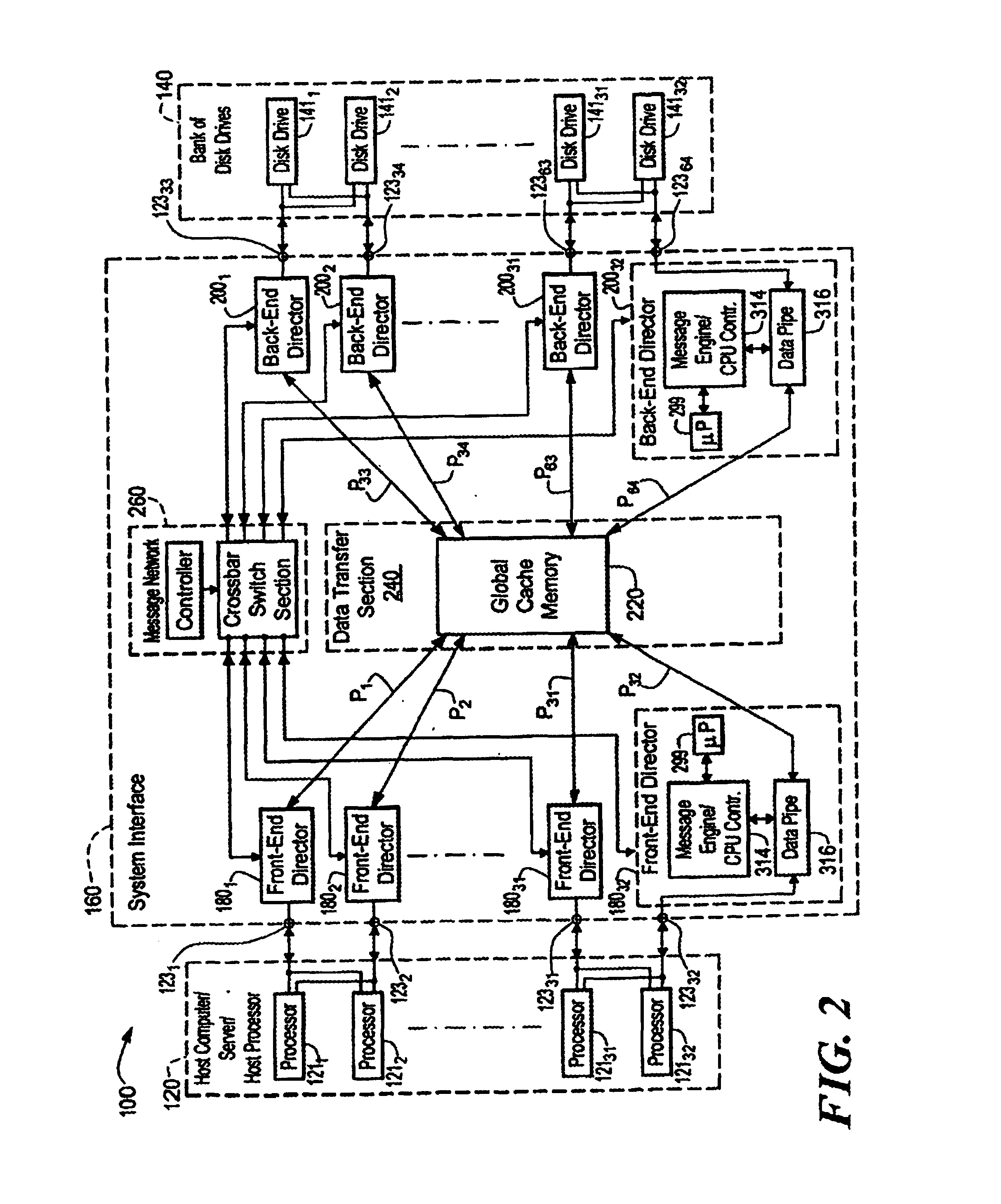
[0010]In accordance with the present invention, a system interface is provided. Such interface includes a plurality of first directors, a plurality of second directors, a data transfer section and a message network. The data transfer section includes a cache memory. The cache memory is coupled to the plurality of first and second directors. The messaging network operates independently of the data transfer section and such network is coupled to the plurality of first directors and the plurality of second directors. The first and second directors control data transfer between the first directors and the second directors in response to messages passing between the first directors and the second directors through the messaging network to facilitate data transfer between first directors and the second directors. The data passes through the cache memory in the data transfer section.

Problems solved by technology

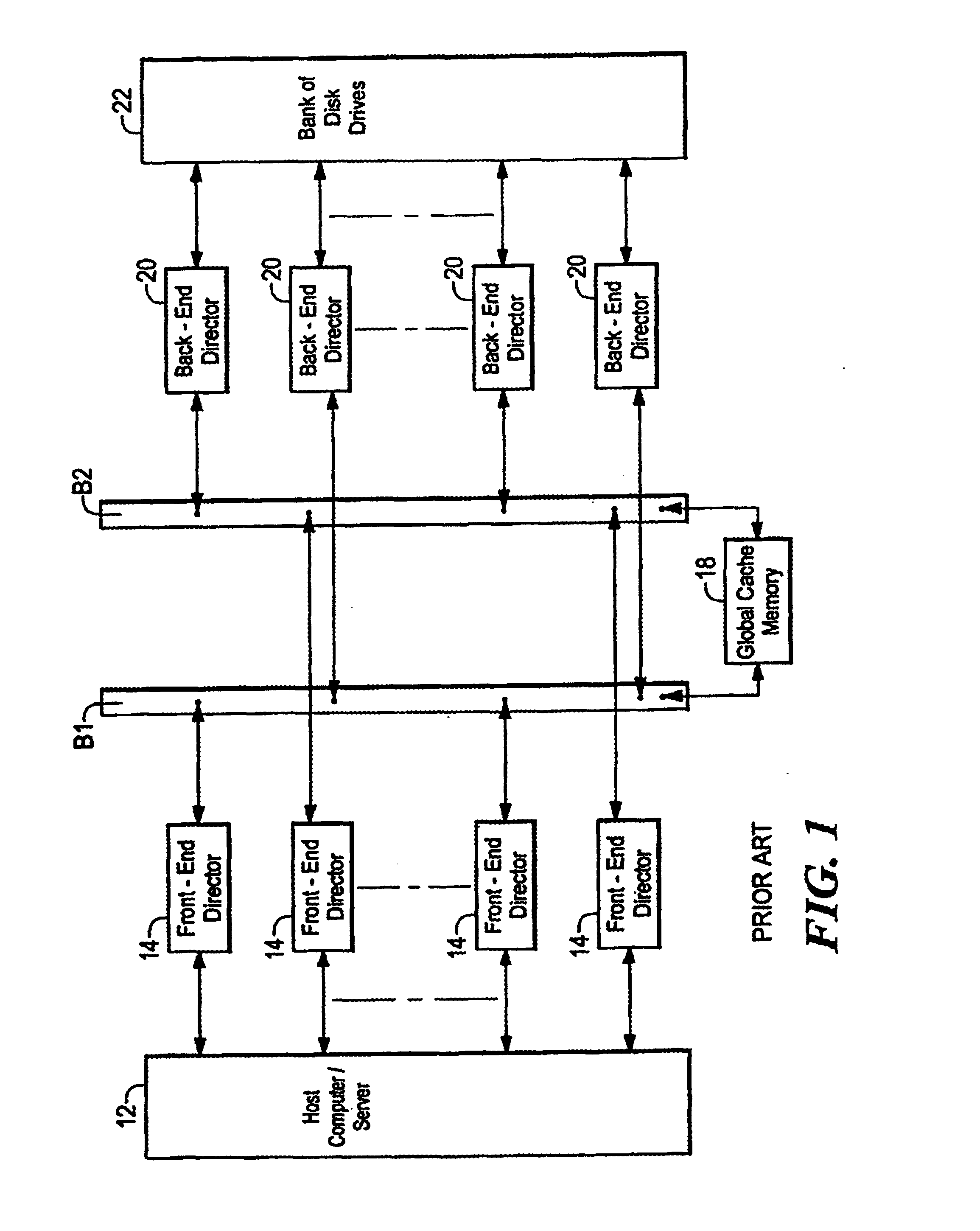
Further, the use of two buses increases the data transfer bandwidth of the system compared to a system having a single bus.

Method used


Image

  • Method for message transfer in computer storage system
  • Method for message transfer in computer storage system
  • Method for message transfer in computer storage system

Examples


Embodiment Construction

[0042]Referring now to FIG. 2, a data storage system 100 is shown for transferring data between a host computer / server 120 and a bank of disk drives 140 through a system interface 160. The system interface 160 includes: a plurality of, here 32 front-end directors 1801-18032 coupled to the host computer / server 120 via ports-12332; a plurality of back-end directors 2001-20032 coupled to the bank of disk drives 140 via ports 12333-12364; a data transfer section 240, having a global cache memory 220, coupled to the plurality of front-end directors 1801-18016 and the back-end directors 2001-20016; and a messaging network 260, operative independently of the data transfer section 240, coupled to the plurality of front-end directors 1801-18032 and the plurality of back-end directors 2001-20032, as shown. The front-end and back-end directors 1801-18032, 2001-20032 are functionally similar and include a microprocessor (μP) 299 (i.e., a central processing unit (CPU) and RAM), a message engine / ...


PUM


Abstract

A system interface includes a plurality of first directors, a plurality of second directors, a data transfer section and a message network. The data transfer section includes a cache memory. The cache memory is coupled to the plurality of first and second directors. The messaging network operates independently of the data transfer section and such network is coupled to the plurality of first directors and the plurality of second directors. The first and second directors control data transfer between the first directors and the second directors in response to messages passing between the first directors and the second directors through the messaging network to facilitate data transfer between first directors and the second directors. The data passes through the cache memory in the data transfer section. A method for operating a data storage system adapted to transfer data between a host computer / server and a bank of disk drives. The method includes transferring messages through a messaging network with the data being transferred between the host computer / server and the bank of disk drives through a cache memory, such message network being independent of the cache memory.

Description

CROSS REFERENCES TO RELATED CASES[0001]This is a divisional application of patent application Ser. No. 09 / 540,828 filed Mar. 31, 2000, which is a continuation in part of patent application Ser. No. 09 / 224,701 filed Jan. 4, 1999, now U.S. Pat. No. 6,061,274 issued May 9, 2000.BACKGROUND OF THE INVENTION[0002]This invention relates generally to data storage systems, and more particularly to data storage systems having redundancy arrangements to protect against total system failure in the event of a failure in a component or subassembly of the storage system.[0003]As is known in the art, large host computers and servers (collectively referred to herein as “host computer / servers”) require large capacity data storage systems. These large computer / servers generally includes data processors, which perform many operations on data introduced to the host computer / server through peripherals including the data storage system. The results of these operations are output to peripherals, including ...

Claims


Application Information

Patent Timeline
IPC IPC(8): G06F3/06
CPCG06F12/0866G06F11/2005G06F11/2089
Inventor BLACK, DAVID L.MACARTHUR, STEPHEN D.WHEELER, RICHARD G.THIBAULT, ROBERT A.SHULMAN, MICHAEL
Owner EMC IP HLDG CO LLC
Learn More