
Modular fitting

a module and fitting technology, applied in the field of fittings, can solve the problems of not enduring high pressure, rise to only small weld seams, and weld seams running longitudinally along the circumference, and achieve the effect of positive effect on the compressive strength of the fitting and/or of the weld seam

Active Publication Date: 2017-05-30
GEORG FISCHER ROHRLEITUNGSSYST
View PDF27 Cites 0 Cited by
  • Summary
  • Abstract
  • Description
  • Claims
  • Application Information

AI Technical Summary

Benefits of technology

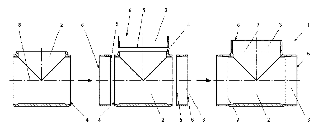
[0008]Since the fittings only have weld seams which run only around the circumference, they meet the stringent requirements in respect of the nominal compressive strength and can readily be installed in pipe systems, which has not been possible up until now using the fitting made of welded pipe segments, since these did not meet the requirements in respect of nominal compressive strength. This is because for example their weld seams, running longitudinally along the circumference, do not withstand high pressures. Furthermore, this geometric construction gives rise to only small weld seams in the case of which there is barely any need to rework the internal diameter, since the small size of the weld seams causes barely any resistance in the line. However, if there is, indeed, a need to remove the weld seams from the inside, this can be done very quickly and straightforwardly.
[0009]The modularity of the fitting allows the production of a large number of different variants of fitting, without this adversely affecting the costs. Even small batches can thus be produced at economically viable costs. The main element, which serves as a basic block, is produced by injection molding, it being possible for different connection elements, in accordance with requirements, to be welded thereto. For example, a main tee part is injection molded, and rectilinear connection elements, produced for example by injection molding, are welded thereto, and it is also possible for reworked pipe sections to be used as the rectilinear connection element. Furthermore, connection elements which have been produced by another method are also suitable here. It is thus possible to dispense with expensive injection molds for a large number of connection elements or else, in production by injection molding, to keep the costs at a very low level by way of a large number of the connection elements being produced, since they fit on all types of main element with the corresponding diameter.
[0016]It is additionally advantageous if different embodiments of connection elements are produced, that is to say if they are designed in accordance with requirements. If, for example, a pipeline which has to be connected to an T-shaped main element has a smaller diameter than that already present in the T-shaped main element, a reducing connection element can be welded to the T-shaped main element. The reducing connection element thus makes it possible to connect even pipelines which have a smaller diameter. Of course, it is also conceivable to have a connection element which is suitable for connection to a pipe with a larger diameter, for example an expansion connection element.
[0018]Use is usually made of rectilinear connection elements, which, on account of their variety of production methods, for example injection molding, severing of a piece of pipe, etc., can be coordinated with the numbers required and are thus highly advantageous for reasons relating to cost.
[0019]A further advantage of the modular construction of the fitting according to the invention consists in that it is possible to weld directly to the main element a connection element which is designed as a welding neck with flange, for example for a valve. This gives rise to very compact installation dimensions since the distance between the end surfaces of the welding neck and the center axis, running parallel thereto, of the T-shaped main element is very short and the appropriate welding neck can be welded directly to the end surface of the T-shaped main element. Conventional tee fittings have relatively long connection stubs since the finished tee fitting is designed with rectilinear connections to which a line is normally connected. If this is not the case, an appropriate adapter part is fitted thereon, as a result of which the installation dimensions of the desired tee fitting, with corresponding coordination with the follow-on component or the follow-on fitting, is extended to a pronounced extent. Such a long distance can, for example, adversely affect the water quality. Since, in the case of branches which do not have constant flow through them, the water becomes stagnant in such dead spaces, and germs therefore readily accumulate there, these germs being entrained with the medium in the event of subsequent flow through the branch, for which reason short connection lengths, such as those provided by the modular construction, are very advantageous. In order to keep such dead spaces as small as possible, the distance which extends between the end surface of the preassembly connection element and / or the welding neck in the direction of the center axis, running parallel thereto, is shorter than the nominal diameter of the corresponding fitting.

Problems solved by technology

Since the fittings only have weld seams which run only around the circumference, they meet the stringent requirements in respect of the nominal compressive strength and can readily be installed in pipe systems, which has not been possible up until now using the fitting made of welded pipe segments, since these did not meet the requirements in respect of nominal compressive strength.
This is because for example their weld seams, running longitudinally along the circumference, do not withstand high pressures.
Furthermore, this geometric construction gives rise to only small weld seams in the case of which there is barely any need to rework the internal diameter, since the small size of the weld seams causes barely any resistance in the line.

Method used


Image

  • Modular fitting
  • Modular fitting
  • Modular fitting

Examples


Embodiment Construction

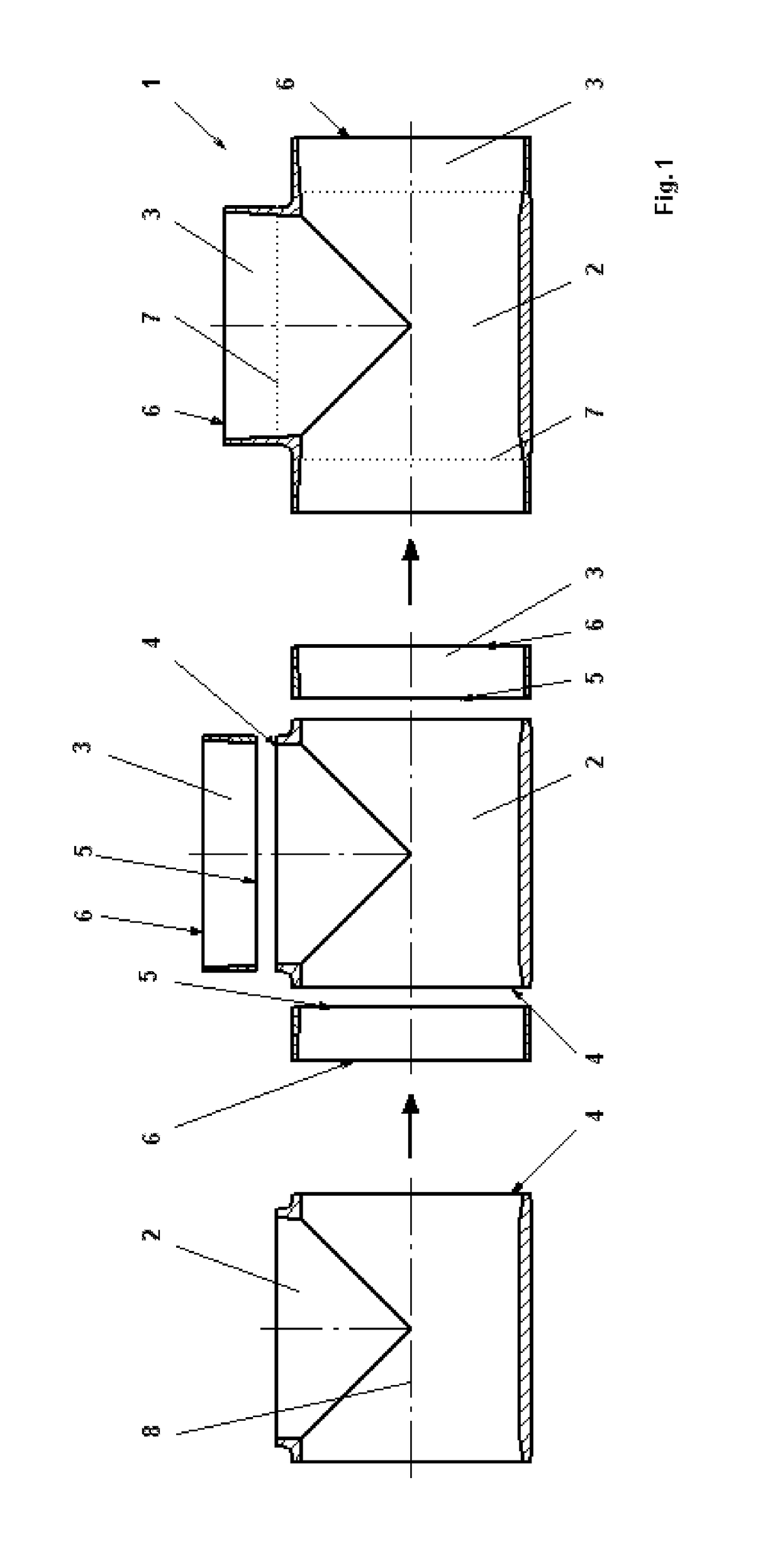
[0030]FIG. 1 shows the modularity of, and the steps for producing, a fitting according to the invention. The left-hand image illustrates a main element 2, which is T-shaped. The main element 2 is usually produced by injection molding, since the main element 2 forms a kind of basic block which withstands increased loading and to which differently designed connection elements 3 or further main elements 2 are welded. The central image illustrates, in addition, the connection elements 3 which can be welded to the main element 2. In the case of the embodiment illustrated, use is made of rectilinear connection elements 3. Of course, it is possible to join on any embodiment of connection element 2 with the corresponding diameter, for example a reducing connection element 10 or an instrument connection element 11, etc. The connection elements 3 are welded by way of their end surface 5, which is round and runs at right angles to the center axis 8, to the end surface 4 of the main element 2, ...


PUM

PropertyMeasurementUnit
diameteraaaaaaaaaa
internal diameteraaaaaaaaaa
internal diametersaaaaaaaaaa

Abstract

A fitting (1) of weldable, thermoplastic material of a modular structure, comprising a number of elements (2, 3, 9, 10, 11, 12), at least one main element (2, 9) and at least one connecting element (3, 10, 11, 12), characterized in that the elements (2, 3, 9, 10, 11, 12) have end faces (4, 5) at right angles to the center axis (8), and the elements (2, 3, 9, 10, 11, 12) are welded to one another exclusively at the end faces (4, 5).

Description

BACKGROUND OF THE INVENTION[0001]The invention relates to a fitting made of weldable, thermoplastic material and having a modular construction, containing a plurality of elements, at least one main element and at least one connection element.[0002]Fittings are understood to be pipeline connectors which connect pieces of pipe to one another and also perform further functions in the process, e.g. changing the direction of the pipe sections which are to be connected. In order to lay a pipeline, it is necessary to use fittings, be this in order to realize branches in the pipelines or in order to deflect the lines by installing bends therein. As far as plastics pipelines are concerned, such fittings are usually produced by injection molding. For reasons relating to cost, injection molding is an ideal method of producing fittings as long as large numbers are required. Injection molding requires an injection mold, which is very complex to produce and is therefore costly. In order to ensure...

Claims


Application Information

Patent Timeline
Patent Type & Authority Patents(United States)
IPC IPC(8): F16L13/02F16L47/32F16L43/00B29C65/00B29C65/02B29K23/00B29K27/06B29K55/02B29K77/00B29K101/12B29L31/24
CPCF16L13/02B29C65/02B29C66/1142B29C66/131B29C66/5223B29C66/52241B29C66/52292F16L43/008F16L47/32B29C66/91221B29K2023/06B29C66/71B29C66/8322B29K2023/12B29K2027/06B29K2055/02B29K2077/00B29K2101/12B29L2031/243B29L2031/246Y10T156/10B29K2027/16B29K2027/12B29K2023/18F16L47/26
Inventor WERMELINGER, JOERG
Owner GEORG FISCHER ROHRLEITUNGSSYST
Learn More