
Compact LCPV solar electric generator

a solar electric generator and compact technology, applied in the direction of solar heat collectors, photovoltaics, solar radiation concentration, etc., can solve the problem of inability to achieve the sizeable increase of power claimed from a compact lcpv device, and achieve the effect of low cost, double the electrical output, and low maintenan

Active Publication Date: 2017-05-23
TAN RAYMOND
View PDF2 Cites 9 Cited by
  • Summary
  • Abstract
  • Description
  • Claims
  • Application Information

AI Technical Summary

Benefits of technology

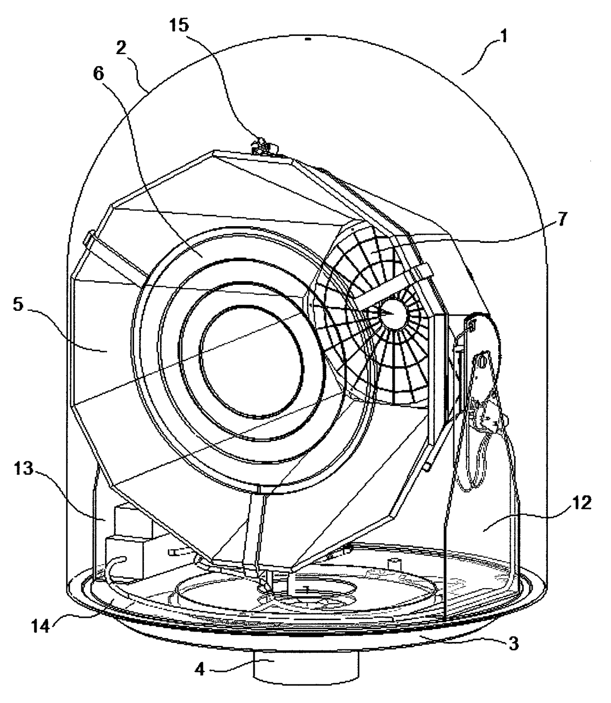
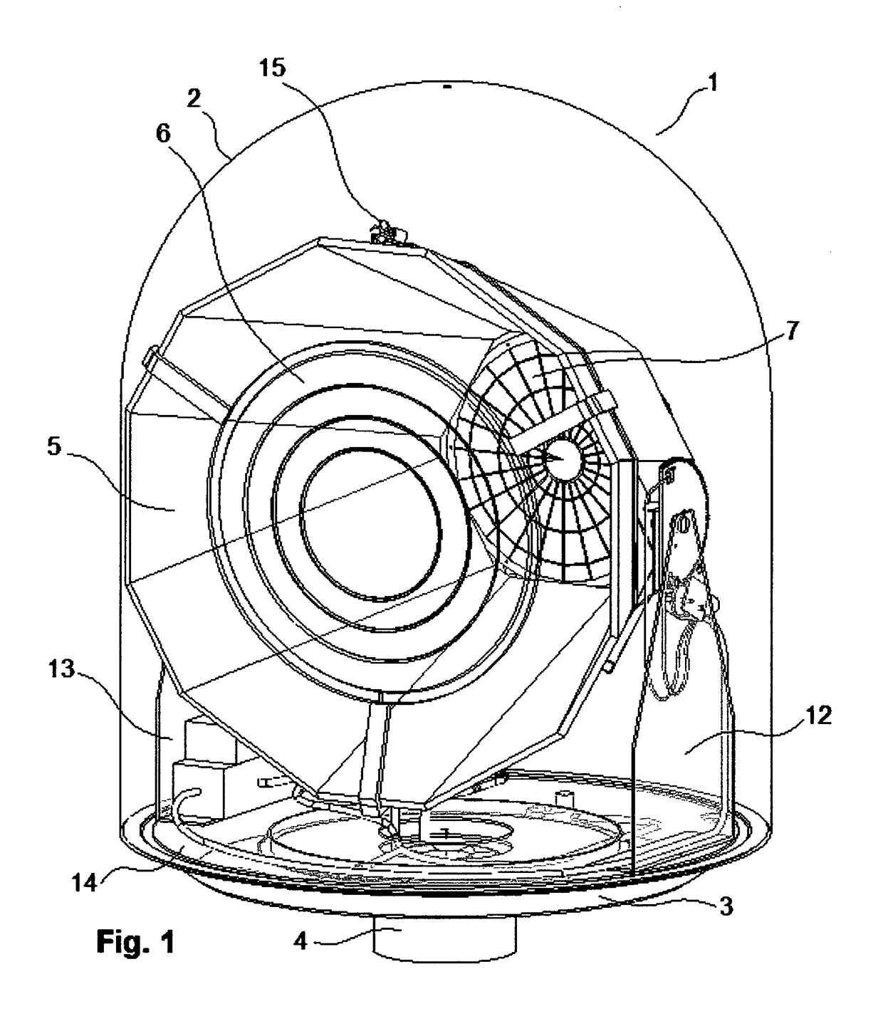
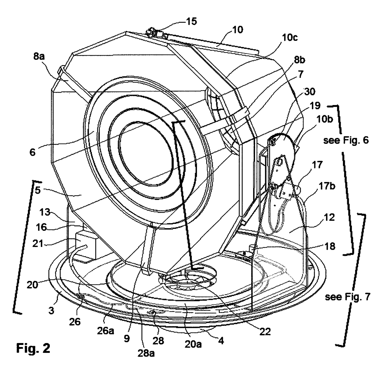
[0042]a biaxial sun position sensor, a biaxial tracker, a biaxial controller and two miniature DC motors with gears to provide short intermittent movements and follow the daily path of the sun.
[0043]and a round exhaust fan mounted at the center bottom of the base for removal of hot humid air that may produce water condensation inside the clear dome in cooler days.
[0047]Another object of this invention is to provide a low cost product for conversion of solar energy into electricity that is user friendly with low maintenance. The tracker operates automatically, unattended making it user friendly. The clear environmental protective dome does not require maintenance for user friendly operation. The present LCPV invention is used in consume r, residential, commercial, and industrial environments to exploit solar concentrators to at least double the electrical output per unit area of deployed solar panel.

Problems solved by technology

This sizeable increase of power claimed from a compact LCPV device was thought not possible by the prior LCPV art.

Method used


Image

  • Compact LCPV solar electric generator
  • Compact LCPV solar electric generator
  • Compact LCPV solar electric generator

Examples


Embodiment Construction

[0080]The present product invention provides a low cost compact LCPV solar electric generator according to attached FIGS. 1 to 16e. An optical assembly composed of a conical mirror and a circular lens is mounted above a flat round PV solar panel inside a conical frame. The whole conical frame assembly rotates with short intermittent movements bi-axially to follow the path of the sun daily. The rotations to follow the sun are reset automatically every twenty four hours. The entire apparatus is environmentally protected against harsh weather with a clear dome mounted on a base. The solar generator works without active thermal management or cooling of the PV solar panel. The present particular configuration of the apparatus is non-obvious compared to configurations of other apparatus from the previous art.

[0081]Reference may be made below to specific elements, numbered in accordance with the attached figures. The discussion below should be taken to be exemplary in nature, and not as li...


PUM


Abstract

A compact low concentration photovoltaic (LCPV) apparatus totally enclosed in a protective clear dome against harsh environment without active cooling. A conical mirror reflector, a circular lens refractor and a planar circular crystalline silicon photovoltaic solar panel rotate simultaneously inside the dome to concentrate sun rays and instantly produce electricity. The mirror increases electrical current three times and the lens increases one time for total four times using low overall concentration of five to twenty times sun. The lens is offset from the plane parallel to the photovoltaic solar panel, while the panels forming the mirror are angled offset to a center axis perpendicular to the solar panel. The optical assembly and solar panel are mounted in a conical aluminum cage which is pivoted from a rotary turntable for the daily azimuth and altitude rotations. The dual axis movements consist of irregular intermittent increments of less than one second “on time” and less than two minutes “off time” while following the sun path. The electrical power produced is at least two times more than from fixed conventional crystalline silicon solar panel occupying the same planar surface area. LCPV dual tracking systems offer reduced electricity generation costs, reduced installation costs and increased flexibility in deployment.

Description

[0001]This is a Continuation-in-Part application of original application Ser. No. 12 / 702,561 Solar Power Generator filed on Feb. 9, 2010.FIELD OF THE INVENTION[0002]This invention relates to an innovative compact LCPV solar electric generator and more specifically to a conical optical configuration of mirror and lens with a planar circular PV solar panel, rotating simultaneously inside a clear protective environmental dome for substantial instantaneous increase in electrical power output.BACKGROUND OF THE INVENTION[0003]Photovoltaic concentrators are known in the industry as high concentration photovoltaic (HCPV), medium concentration photovoltaic (MCPV) and low concentration photovoltaic (LCPV). These concentrators operate mostly with a dual axis tracker to point the apparatus toward the sun. Photovoltaic cells comprising of semiconductor junctions as p-n junctions are used. It is well known that light with photon energy greater than the band gap of an absorbing semiconductor layer...

Claims


Application Information

Patent Timeline
Patent Type & Authority Patents(United States)
IPC IPC(8): H01L31/00H01L31/052F24J2/08F24J2/10F24J2/54G02B19/00H01L31/054H01L31/042H02S20/32F24J2/46F24S23/30F24S23/70
CPCH01L31/052F24J2/085F24J2/10F24J2/5417G02B19/0042H01L31/0543H01L31/0547H02S20/32F24J2/4609F24J2/4621G02B19/0028Y02E10/43Y02E10/47Y02E10/52Y02B10/20F24S23/31F24S23/70F24S40/10F24S40/50F24S30/45
Inventor TAN, RAYMOND
Owner TAN RAYMOND
Learn More