Vertical-takeoff aircraft

a vertical-to-wing aircraft technology, applied in the direction of vertical landing/take-off aircraft, transportation and packaging, gas production bioreactors, etc., can solve the problems of only slightly affecting the flying behavior, unsteady flying behavior during vertical flying, etc., and achieve the effect of good flying behavior and cost-effective design

Active Publication Date: 2017-05-09
WINGCOPTER GMBH
View PDF10 Cites 67 Cited by
  • Summary
  • Abstract
  • Description
  • Claims
  • Application Information

AI Technical Summary

Benefits of technology

[0004]It is also known to provide separate supporting elements for the drive units on the wings, wherein one separate supporting element is arranged rigidly above the wing, and one separate supporting element is arranged rigidly below the wing, on the wing. In this manner, the flows from the drive units do not approach each other in the horizontal flying position, and therefore the efficiency in the horizontal flying position is improved. Since the drive units are arranged at different heights, the drive units have, however, different ground effects in the vicinity of the ground during vertical flying, wherein a lift emanating from the drive unit arranged lower is customarily greater than a lift from the drive unit arranged higher. The drive power of the drive units arranged at different heights therefore has to be constantly readjusted during vertical flying. This leads to an unsteady flying behavior during vertical flying.
[0015]A particularly cost-effective design and particularly good flying behavior are achieved according to the invention by the first drive unit and the second drive unit being propeller drives or impeller drives or jet engines. Propeller drives are expediently formed rigidly or with rotor blade adjustment.

Problems solved by technology

This leads to an unsteady flying behavior during vertical flying.
However, slight deviations from such an arrangement, which can be attributed, for example, to manufacturing tolerances, impair the flying behavior only slightly, if at all.

Method used


Image

  • Vertical-takeoff aircraft
  • Vertical-takeoff aircraft
  • Vertical-takeoff aircraft

Examples


Embodiment Construction

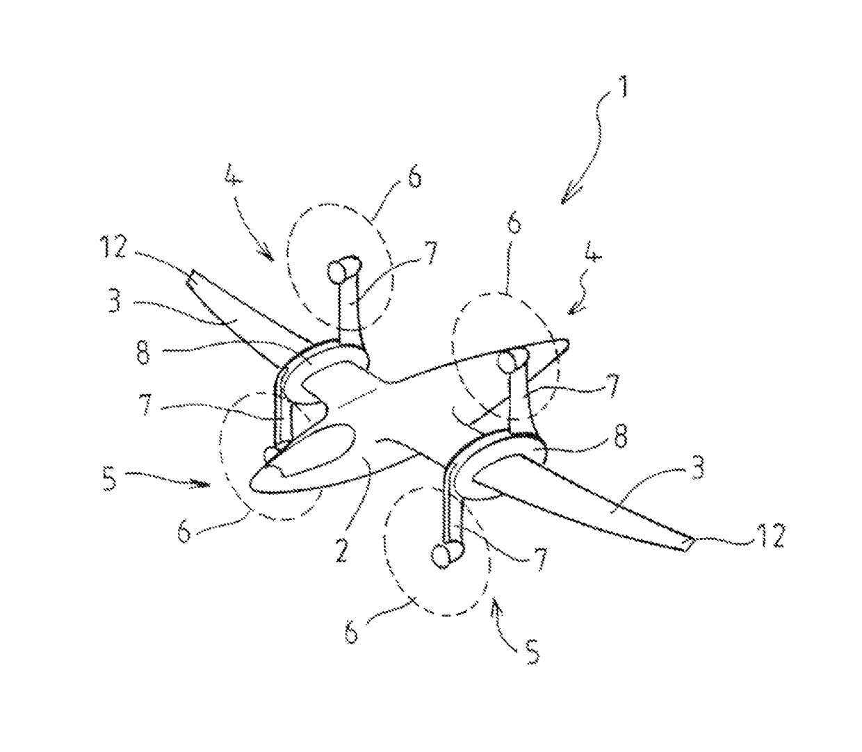
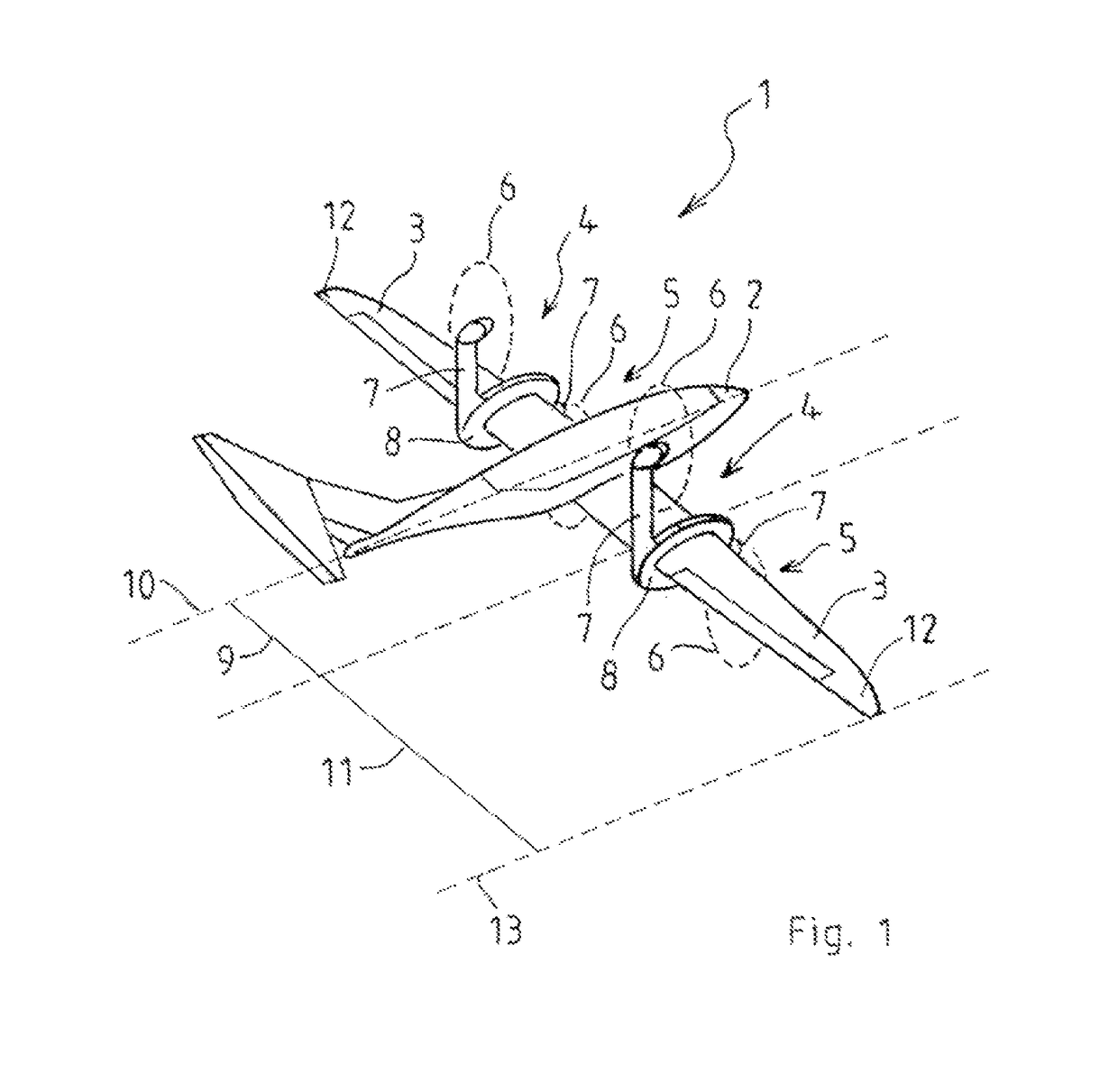
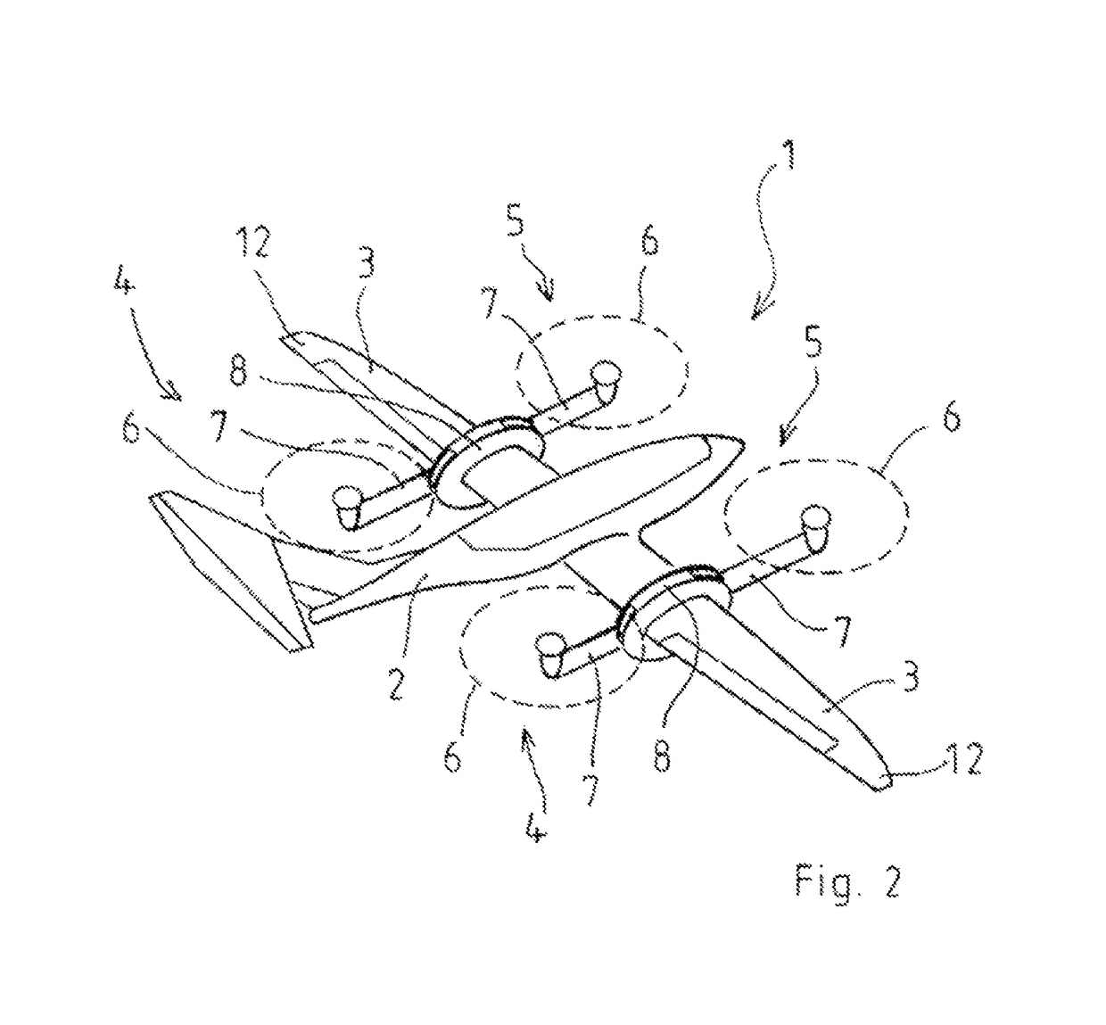
[0024]FIGS. 1 and 2 show schematic illustrations of vertical-takeoff aircraft 1 with a wing 3 arranged in each case on opposite sides of a fuselage 2. A first drive unit 4 and a second drive unit 5 are in each case arranged mounted pivotably on the wings 3. The first drive unit 4 and the second drive unit 5 each have a propeller 6 and a pivoting arm 7. The pivoting arms 7 are arranged pivotably on the wings 3, wherein a coupled pivoting movement of pivoting devices 8 arranged on the wings 3 is triggered and driven.

[0025]The first drive unit 4 and the second drive unit 5 are arranged on the wings 3 in such a manner that a fuselage distance 9 of the drive units 4 and 5 from a longitudinal axis 10 of the vertical-takeoff aircraft 1 is smaller than a wing end distance 11 of the first drive unit 4 and of the second drive unit 5 from a wing axis 13 which runs through a wing end 12 and is parallel to the longitudinal axis 10.

[0026]In FIG. 1, the first drive unit 4 and the second drive unit...


PUM


Abstract

A vertical-takeoff aircraft with a wing. A first drive unit and a second drive unit are swivellably mounted on the wing. The first drive unit and the second drive unit are arranged on the wing at a distance from a wing-end of the wing. A first distance between the first drive unit and a longitudinal axis of the aircraft is approximately equal to a second distance between the second drive unit and the longitudinal axis of the aircraft. The first drive unit and the second drive unit are swivellable into a horizontal flying position and a vertical flying position. In the horizontal flying position the first drive unit is arranged above a wing surface and the second drive unit below the wing surface on the wing. In the vertical flying position the first drive unit and the second drive unit are arranged in an approximately horizontal plane. The first drive unit and the second drive unit each have a swivel arm, wherein the swivel arms are swivellably mounted on the wing.

Description

BACKGROUND AND SUMMARY[0001]The invention relates to a vertical-takeoff aircraft with a wing, wherein a first drive unit and a second drive unit are arranged mounted pivotably on the wing, wherein the first drive unit and the second drive unit are arranged on the wing at a distance from one end of the wing, wherein a first distance of the first drive unit from a longitudinal axis of the aircraft is approximately identical to a second distance of the second drive unit from the longitudinal axis of the aircraft, and wherein the first drive unit and the second drive unit are pivotable into a horizontal flying position and a vertical flying position.[0002]Vertical-takeoff aircrafts are used, inter alia, as drones and in the military sphere. These aircrafts customarily have two wings arrange on opposite sides of a fuselage, wherein in each case two drive units are arranged mounted pivotably on the wings in supporting elements which are adapted to the particular intended use and are conne...

Claims


Application Information

Patent Timeline
Patent Type & Authority Patents(United States)
IPC IPC(8): B64C29/00B64C11/46B64D27/26
CPCB64C29/0033B64C11/46B64C29/0075B64D27/26B65D90/08C12M21/04C12M23/46B64C27/28B64C29/00
Inventor HESSELBARTH, JONATHAN
Owner WINGCOPTER GMBH
Why Eureka
Try Eureka