Imaging-capturing and light-sensing optical apparatus

a technology of optical apparatus and light sensor, applied in the field of optical apparatus, can solve the problems of increasing the length of the casing, and affecting the efficiency of guiding, so as to achieve the effect of enhancing the functionality of the optical apparatus

Active Publication Date: 2017-04-25
ATLANTIC BRIDGE INC +1
View PDF6 Cites 0 Cited by
  • Summary
  • Abstract
  • Description
  • Claims
  • Application Information

AI Technical Summary

Benefits of technology

[0007]An objective of the present invention provides an integrated optical apparatus capable of implementing different functions at the same time. Consequently, the functionality of the optical apparatus is enhanced.
[0013]In an embodiment, if the first viewing zone of the first optical lens is rectangular or nearly-rectangular and an object to be captured is near the first optical lens module, the size of the first opening satisfies mathematic formulae:RaM,x≅WM·tan θM,x−RsM,x, RaM,x≦R*aM,x;RaM,y≅WM·tan θM,y−RsM,y, RaM,y≦R*aM,y;wherein if the first viewing zone of the first optical lens is rectangular or nearly-rectangular and the object to be captured is far from the first optical lens module, the size of the first opening satisfies mathematic formulae:RaM,x≅fM·tan θM,x−RsM,x, RaM,x≦R*aM,x;RaM,y≅fM·tan θM,y−RsM,y, RaM,y≦R*aM,y;wherein R*aM,x is a half length of the first opening along a first direction, R*aM,y is a half length of the first opening along a second direction, WM is a first working distance of the first optical lens module, RaM,x is a half length of the first optical lens along the first direction, RaM,y is a half length of the first optical lens along the second direction, θM,x is the first field angle of the first optical lens along the first direction, θM,y is the first field angle of the first optical lens along the second direction, RsM,x is a half length of the first optical sensor along the first direction, RsM,y is a half length of the first optical sensor along the second direction, and fM is a first equivalent focal length of the first optical lens module. Once the above relations are fulfilled, the minimization of system size could be achieved without a loss of system performance.
[0015]In an embodiment, if the second viewing zone of the second optical lens is circular or nearly-circular and an object to be sensed is near the second optical lens module, the size of the second opening satisfies mathematic formulae:RaA≅WA·tan θA−RLA, and RaA≦R*aA,wherein if the second viewing zone of the second optical lens is circular or nearly-circular and the object to be sensed is far from the second optical lens module, the size of the second opening satisfies mathematic formulae:RaA≅fA·tan θA−RLA, and RaA≦R*aA,wherein R*aA is a radius of the second opening, WA is a second working distance of the second optical lens module, RaA is a radius of the second optical lens, θA is the second field angle of the second optical lens, RLA is a radius of the first surface of the light guide element, and fA is a second equivalent focal length of the second optical lens module. Once the above relations are fulfilled, the minimization of system size could be achieved without a loss of system performance.
[0016]In an embodiment, if the second viewing zone of the second optical lens is rectangular or nearly-rectangular and an object to be sensed is near the second optical lens module, the size of the second opening satisfies mathematic formulae:RaA,x≅WA·tan θA,x−RLA,x, RaA,x≦R*aA,x,RaA,y≅WA·tan θA,y−RLA,y, RaA,y≦R*aA,y,wherein if the second viewing zone of the second optical lens is rectangular or nearly-rectangular and the object to be sensed is far from the second optical lens module, the size of the second opening satisfies mathematic formulae:RaA,x≅fA·tan θA,x−RLA,x, RaA,x≦R*aA,x;RaA,y≅fA·tan θA,y−RLA,y, RaA,y≦R*aA,y;wherein R*aA,x is a half length of the second opening along a first direction, R*aA,y is a half length of the second opening along a second direction, WA is a second working distance of the second optical lens module, RaA,x is a half length of the second optical lens along the first direction, RaA,y is a half length of the second optical lens along the second direction, θA,x is the second field angle of the second optical lens along the first direction, θA,y is the second field angle of the second optical lens along the second direction, RLA,x is a half length of the first surface of the light guide element along the first direction, RLA,y is a half length of the first surface of the light guide element along the first direction, and fA is a second equivalent focal length of the second optical lens module. Once the above relations are fulfilled, the minimization of system size could be achieved without a loss of system performance.
[0028]From above descriptions, the present invention provides an image-capturing and light-sensing optical apparatus. The above mathematic formulae can be used to determine the maximum field of view and generate the maximum viewing zone according to the size of the first optical lens, the size of the second optical lens, the size of the first optical sensor and the size of the light guide element. Moreover, the sizes of the corresponding openings of the casing are determined according to the sizes of these optical lenses. Once the above conditions are fulfilled, the minimization of system size could be achieved without a loss of system performance. Since the image-capturing and light-sensing optical apparatus is designed according to the above mathematic formulae, the field of view is larger and the casing is slimmer. Under this circumstance, the image-capturing and light-sensing optical apparatus complies with the purpose of miniaturization. Consequently, the image-capturing and light-sensing optical apparatus of the present invention can be applied to a portable electronic device such as a smart phone, a tablet computer or a wearable device.

Problems solved by technology

However, with the maturity of the sensing devices and the image capturing devices, the overall structures are complicated and bulky.
However, a longer light guide element has impaired guiding efficiency and higher cost, and the arrangement of the longer light guide element also increases the length of the casing 13.

Method used


Image

  • Imaging-capturing and light-sensing optical apparatus
  • Imaging-capturing and light-sensing optical apparatus
  • Imaging-capturing and light-sensing optical apparatus

Examples


Embodiment Construction

[0039]For overcoming the drawbacks of the conventional technologies, the present invention provides an image-capturing and light-sensing optical apparatus.

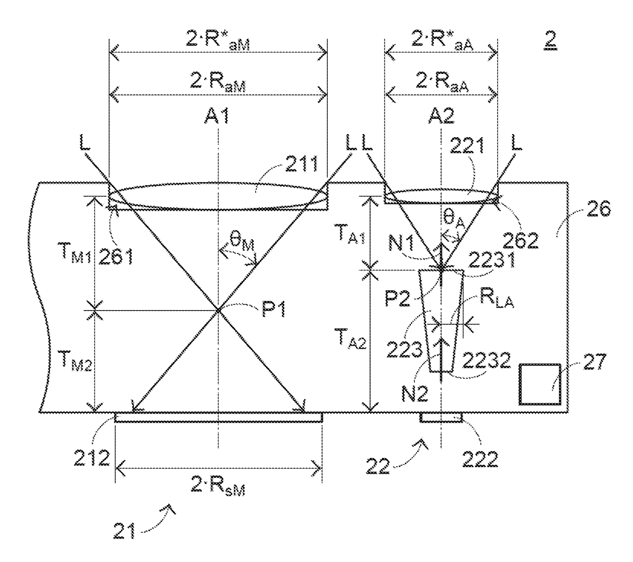
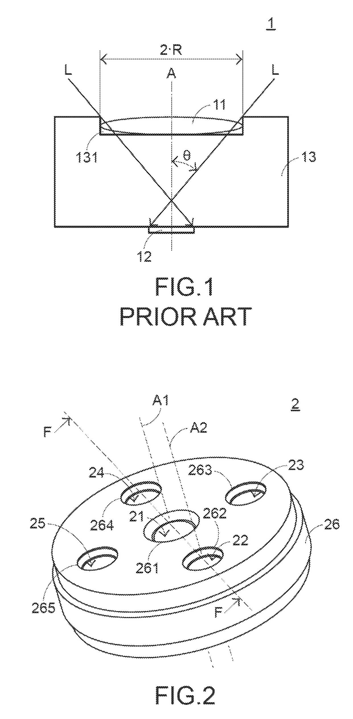
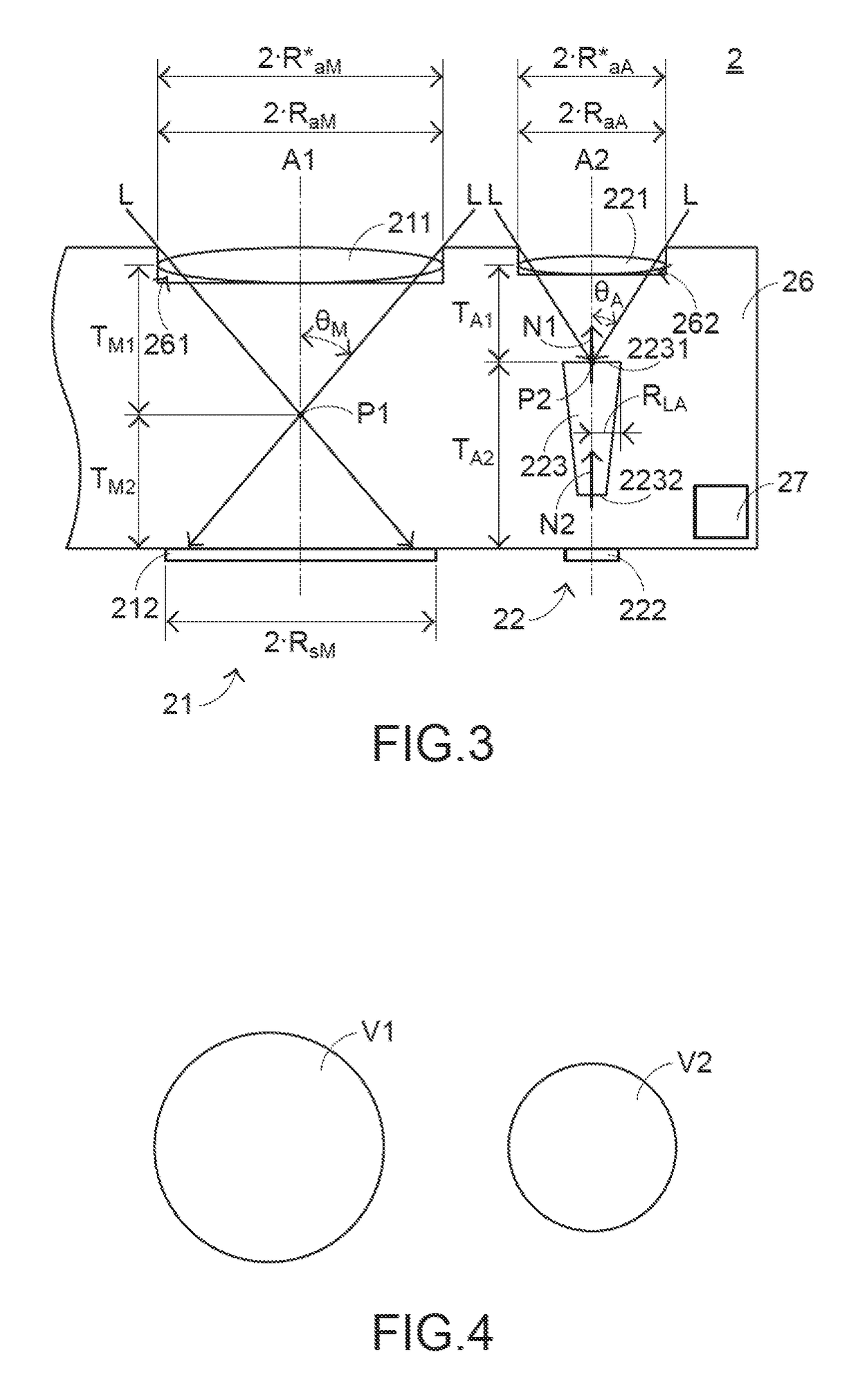
[0040]Please refer to FIGS. 2, 3 and 4. FIG. 2 is a schematic perspective view illustrating the outer appearance of an image-capturing and light-sensing optical apparatus according to a first embodiment of the present invention. FIG. 3 is a schematic cross-sectional view illustrating a portion of the image-capturing and light-sensing optical apparatus of FIG. 2 and taken along the line F. FIG. 4 schematically illustrating a first viewing zone and a second viewing zone of the image-capturing and light-sensing optical apparatus according to the first embodiment of the present invention. The image-capturing and light-sensing optical apparatus 2 comprises a first optical lens module 21, a second optical lens module 22, a third optical lens module 23, a fourth optical lens module 24, a fifth optical lens module 25, a casing 26 and a mo...


PUM


Abstract

An image-capturing and light-sensing optical apparatus has both of an image capturing function and a light sensing function. The image-capturing and light-sensing optical apparatus includes a first optical lens module, a second optical lens module and a casing. The casing has a first opening. The first optical lens module includes a first optical lens and a first optical sensor. According to the working distance or the equivalent focal length of the first optical lens module, the size of the first optical lens and the size of the first optical sensor, the maximum field of view is acquired. Consequently, the size of the first opening is determined, and the casing is slim. Under this circumstance, the image-capturing and light-sensing optical apparatus complies with the purpose of miniaturization.

Description

FIELD OF THE INVENTION[0001]The present invention relates to an optical apparatus, and more particularly to an integrated optical apparatus in which an image capturing function and a light sensing function can operate simultaneously and correspondingly.BACKGROUND OF THE INVENTION[0002]Recently, with the development of science and technology, many opto-electronic / electronic devices are designed toward small size, light weightiness and easy portability. Consequently, these opto-electronic / electronic devices can be applied to mobile business, entertainment or leisure purposes whenever or wherever the users are. In these devices, function of image capturing has been a standard assignment and playing a basic functional unit. Indeed, various image capturing devices are widely used in many kinds of systems such as smart phones, tablet computers, wearable devices or any other appropriate electronic devices, modules, or systems. Since the image capturing devices are small and portable, the u...

Claims


Application Information

Patent Timeline
Patent Type & Authority Patents(United States)
IPC IPC(8): H04N9/73G01J1/04G02B7/08G02B13/00H04N5/225G02B7/02
CPCG02B7/021G01J1/0411G01J1/0425G02B7/08G02B13/001H04N5/2252H04N5/2253H04N5/2254G01J1/0271G01J1/0422G01J1/0204G02B3/0043G01J1/0266H04N23/51H04N23/54
Inventor CHERN, JYH-LONGYEN, CHIH-MING
Owner ATLANTIC BRIDGE INC
Why Eureka
Try Eureka