
Communication system, relay device, and method for controlling power supply

a technology of relay device and power supply, applied in the field of communication system, can solve problems such as excessive commutation resource usage, and achieve the effect of simple processing

Inactive Publication Date: 2017-04-11
AUTONETWORKS TECH LTD +2
View PDF26 Cites 0 Cited by
  • Summary
  • Abstract
  • Description
  • Claims
  • Application Information

AI Technical Summary

Benefits of technology

The present invention is a relay device that extracts and collects information required for power supply control, and then transmits it to a power supply control device. This simplifies the configuration of the power supply control device, as it does not need to execute processing of obtaining required information from multiple information groups. The relay device can grasp information of the whole system to perform power supply control, appropriately balancing power savings and preventing battery exhaustion. Additionally, the relay device does not determine the necessity of transmitting information for each communication device, reducing communication load and simplifying the overall communication system.

Problems solved by technology

In addition, unnecessary information is also transmitted to the ECU 95, resulting in excessive usage of commutation resources.

Method used


Image

  • Communication system, relay device, and method for controlling power supply
  • Communication system, relay device, and method for controlling power supply
  • Communication system, relay device, and method for controlling power supply

Examples


embodiment 1

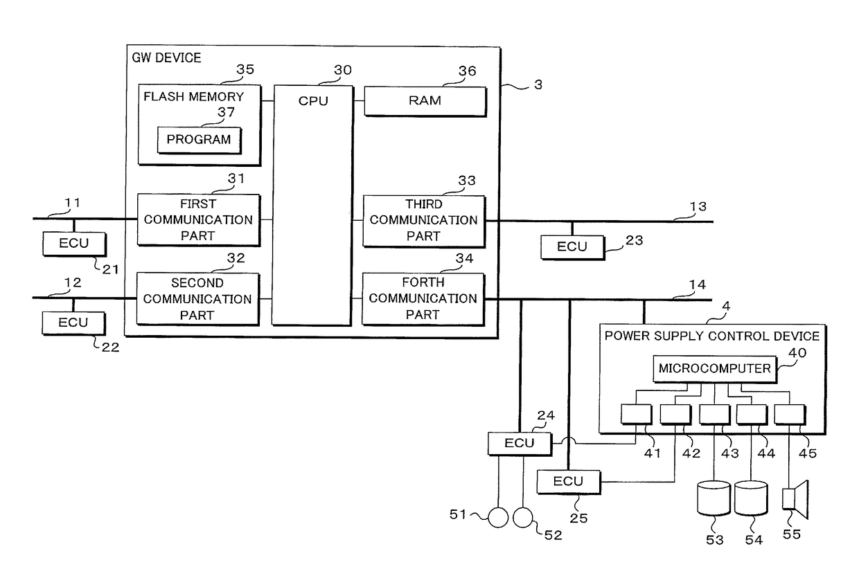
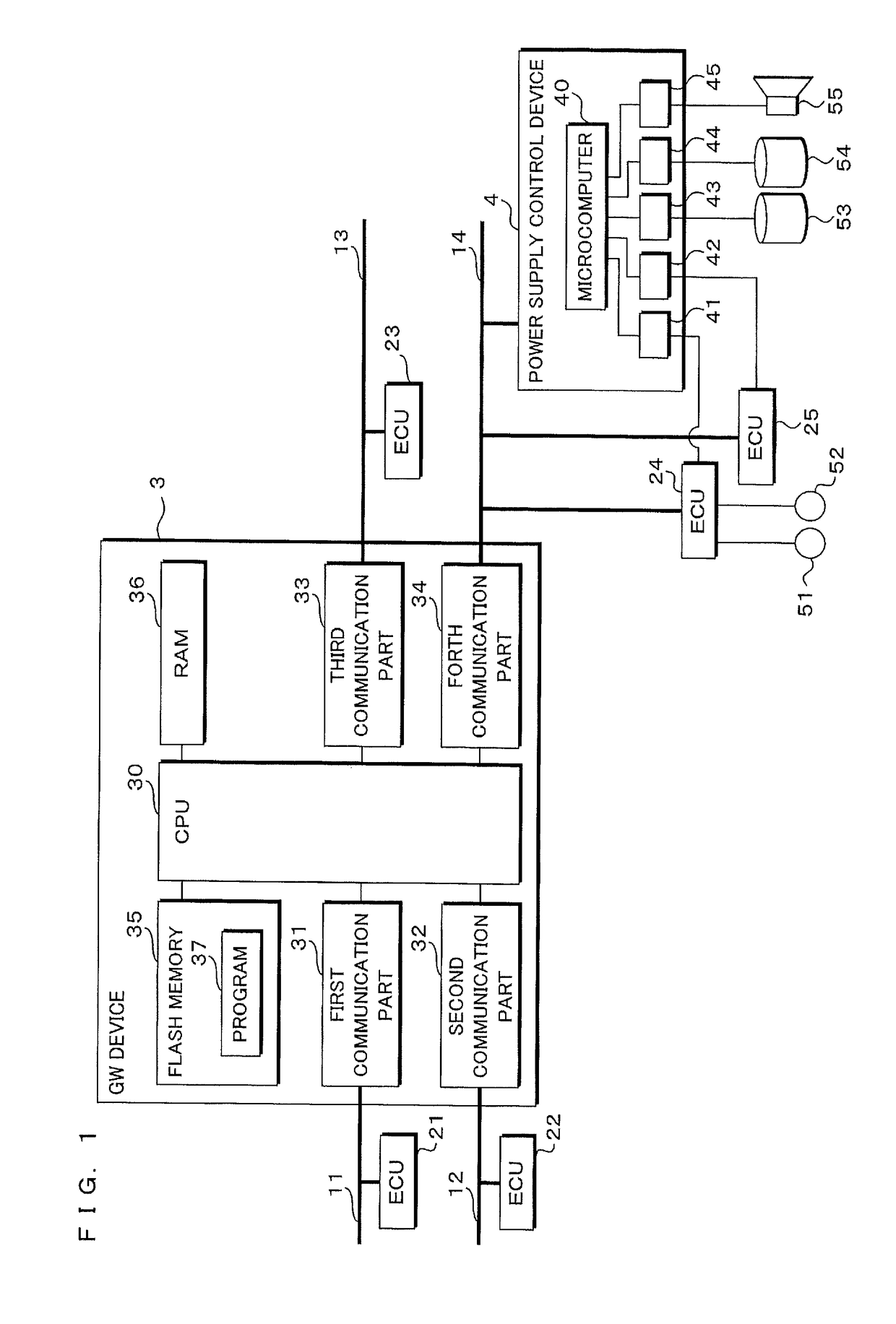
[0053]FIG. 1 is a block diagram that shows the configuration of an on-vehicle communication system according to Embodiment 1.

[0054]The on-vehicle communication system includes a plurality of communication buses 11 to 14, ECUs 21 to 25 respectively connected to the communication buses 11 to 14 for controlling devices, a GW (Gate Way) device 3 executing relay processing for information among the communication buses 11 to 14, a power supply control device 4 executing power supply control of each device, and loads 51 to 55 to be controlled.

[0055]In Embodiment 1, communication via any of the communication buses 11 to 14 is compliant with a CAN protocol. The plurality of communication buses 11 to 14 are discriminated by the types of subjects to be controlled by the connected ECUs 21 to 25. In other words, the plurality of communication buses 11 to 14 are discriminated by the types of information to be transmitted or received. A communication speed may be set differently for each of the co...

embodiment 2

[0084]In Embodiment 1, the GW device 3 is configured to create a CAN message including signal information extracted from the received CAN message as it is when the GW device 3 creates a CAN message related to power supply control. In Embodiment 2, the GW device 3 creates control information for providing an instruction to turn power on / off based on the extracted signal, and then creates a CAN message including the control information and transmits it.

[0085]FIG. 6 is a block diagram that shows the configuration of an on-vehicle communication system according to Embodiment 2. In Embodiment 2, the GW device 3 stores an on / off table 38 into the flash memory 35. The configuration of the on-vehicle communication system according to Embodiment 2 is similar to the configuration according to Embodiment 1 except the GW device 3 comprising the on / off table 38 and the detailed parts of the following relay processing. Accordingly, the same reference numerals are appended to the similar configura...

embodiment 3

[0094]In Embodiment 3, the GW device 3 comprehensively specifies the vehicle state based on not only a CAN message transmitted to the communication buses 11 to 14, but also the information obtained from sensors and switches mounted within a vehicle and the out-of-vehicle communication and creates information related to power supply control corresponding to the specified vehicle state and then transmits the created information to the power supply control device 4.

[0095]FIG. 10 is a block diagram that shows the configuration of an on-vehicle communication system according to Embodiment 3. In Embodiment 3, the GW device 3 further includes an input / output part 39 connected to a sensor 56 and a switch 57, a first out-of-vehicle communication part 61 and a second out-of-vehicle communication part 62. The GW device 3 according to Embodiment 3 stores the vehicle state table 63 and the on / off table 64 into the flash memory 35. The configuration of the GW device 3 according to Embodiment 3 is...


PUM


Abstract

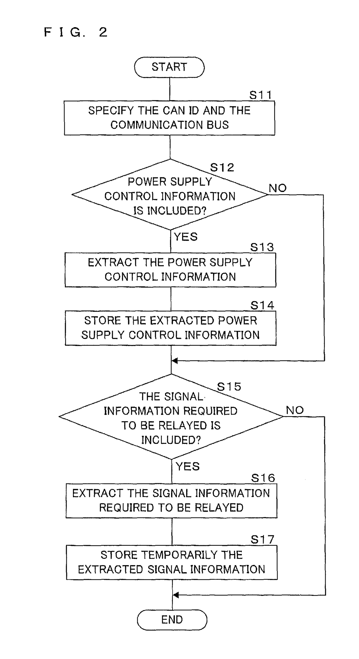
The present invention provides a communication system including a relay device that is capable of simplifying the configuration of a control device for controlling a device based on relay information and reducing cost of the whole system, the relay device and a method for controlling power supply. A GW device includes first to fourth communication parts respectively connected to communication buses, which are connected to ECUs respectively. The GW device receives a message transmitted from each of ECUs, extracts signal information S1 to S5 related to equipment in the vehicle included in the message from the received message, collects the extracted signal information S1 to S5 to create a message (ID4), and transmits the created message to a power supply control device. The power supply control device controls on / off of the ECUs and each of loads based on signal information included in the message received from the GW device.

Description

[0001]This application is the national phase under 35 U.S.C. §371 of PCT International Application No. PCT / JP2013 / 052006 which has an International filing date of Jan. 30, 2013 and designated the United States of America.BACKGROUND OF THE INVENTION[0002]1. Field of the Invention[0003]The present invention relates to a communication system that includes a relay device for a relay of information among different communication buses. In particular, the present invention relates to a communication system capable of properly controlling power supply of the system while simplifying the configuration of a control device for controlling devices based on information to be relayed, a relay device constituting the communication system, and a method for controlling power supply of devices in the communication system.[0004]2. Description of Related Art[0005]In the technical field of vehicle control, the configuration in which several electronic control units (ECU) for respectively controlling dev...

Claims


Application Information

Patent Timeline
Patent Type & Authority Patents(United States)
IPC IPC(8): G06F1/32H04L12/46H04L12/40H04L12/66H04L12/64H04L12/12
CPCG06F1/3243G06F1/3287H04L12/12H04L12/40039H04L12/4625H04L12/6418H04L12/66H04L2012/40215H04L2012/40273Y02B60/34Y02D30/50
Inventor HORIHATA, SATOSHI
Owner AUTONETWORKS TECH LTD
Learn More