
Method, devices and systems for sensor with removable nodes

a sensor and node technology, applied in the field of methods, devices and systems for sensors with removable nodes, can solve the problems of large existing wireless sensors, large disadvantages of existing sensors and sensor networks, and inability to meet the needs of patients,

Active Publication Date: 2017-04-11
PHILIPS HEALTHCARE INFORMATICS INC
View PDF6 Cites 7 Cited by
  • Summary
  • Abstract
  • Description
  • Claims
  • Application Information

AI Technical Summary

Benefits of technology

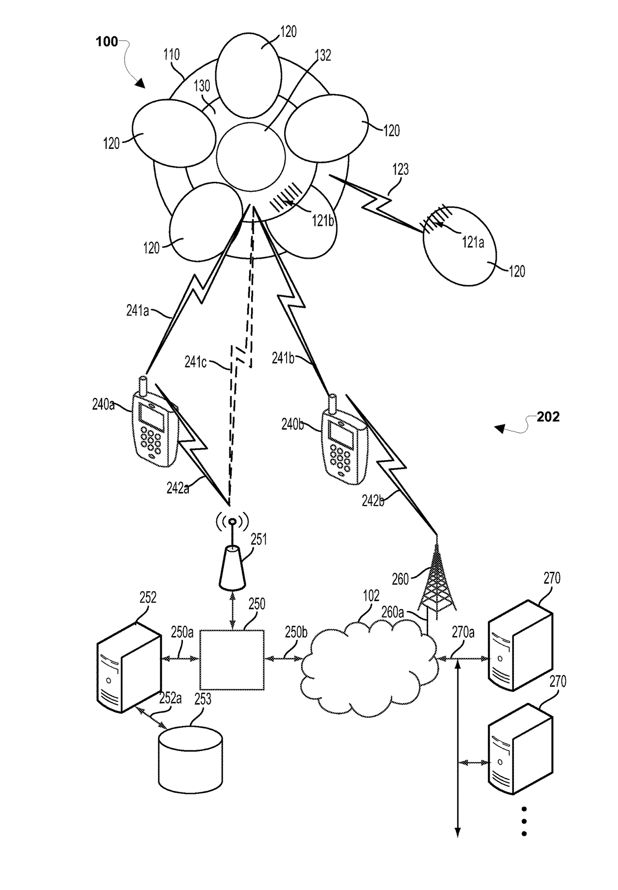
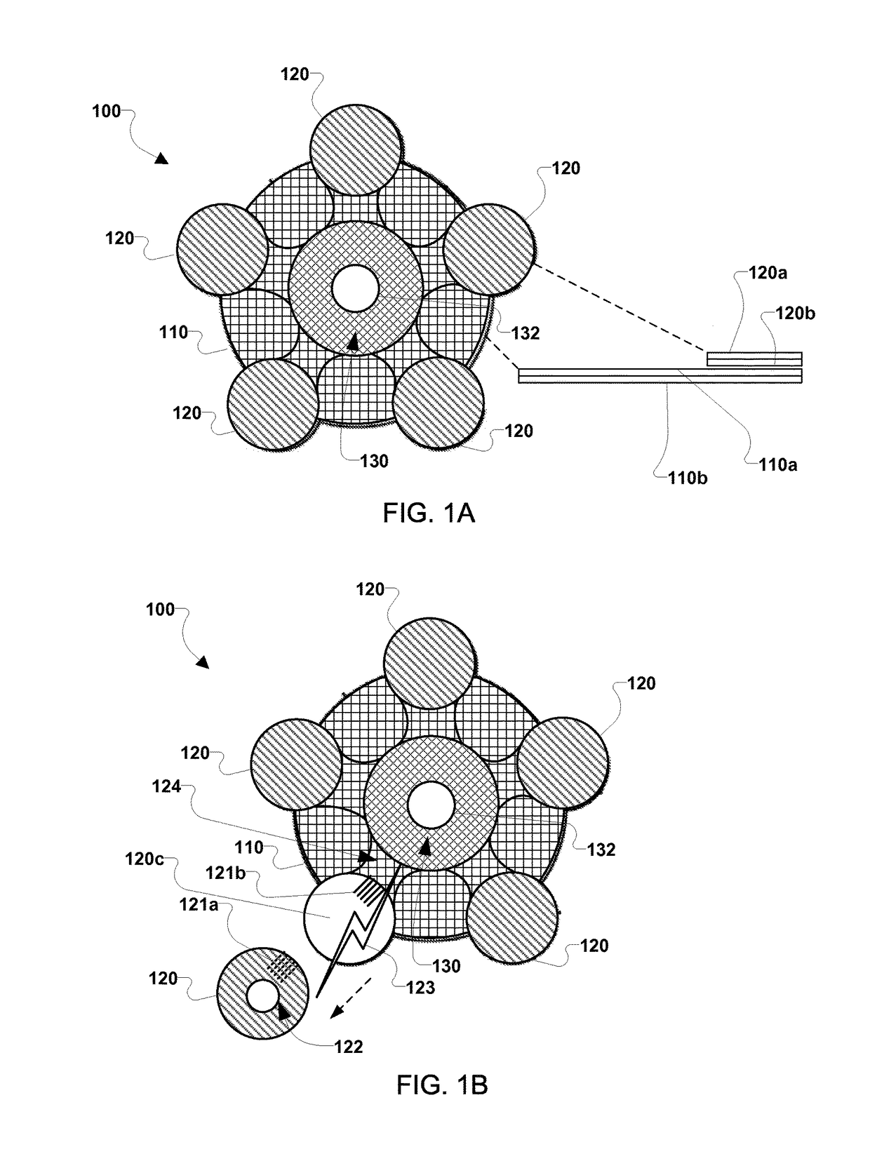
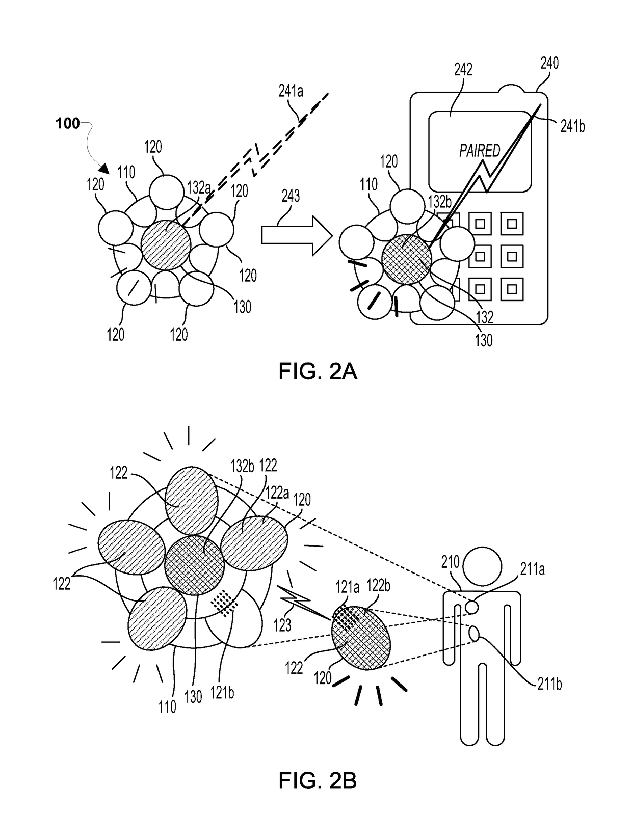
The patent describes a device for measuring physical or physiological parameters of a body. The device includes a flexible adhesive sensor array with a sensor hub and a detachable sensor pod. The detachable sensor pod can be attached to the sensor hub and powered by the sensor hub. The sensor pod has a flexible layer integrated with the flexible adhesive substrate and a connector for attaching it to the sensor hub. The sensor hub has a wireless transceiver, energy storage, and a processor for performing various operations. The detachable sensor pod has a sensor, energy storage, and a transmitter for transmitting sensor data to the sensor hub. The sensor hub can provide indications regarding proper placement of the detachable sensor pod on the body. The device can be used for various medical or healthcare applications.

Problems solved by technology

While wireless sensors provide some degree of convenience, challenges remain.
In view of these challenges, disadvantages for existing sensors and sensor networks are numerous.
Existing wireless sensors may be large, have limited longevity, limited battery life, and may not monitor all of the desired parameters.
As adhesive sensors may be uncomfortable for the wearer, a large sensor size may be a disadvantage.
Further, multiple large sensors may become cumbersome for the wearer.
As a result, separate network support for the different sensors may be required raising costs and complexity.

Method used


Image

  • Method, devices and systems for sensor with removable nodes
  • Method, devices and systems for sensor with removable nodes
  • Method, devices and systems for sensor with removable nodes

Examples


Embodiment Construction

[0028]The various embodiments will be described in detail with reference to the accompanying drawings. Wherever possible, the same reference numbers will be used throughout the drawings to refer to the same or like parts. References made to particular examples and implementations are for illustrative purposes, and are not intended to limit the scope of the invention or the claims.

[0029]The terms “device,”“computing device,”“mobile computing device,” as used herein, may refer to any one or all of cellular telephones, smartphones, personal or mobile multi-media players, personal data assistants (PDA's), laptop computers, desktop computers, tablet computers, smart books, palm-top computers, wireless electronic mail receivers, multimedia Internet enabled cellular telephones, televisions, smart TVs, smart TV set-top buddy boxes, integrated smart TVs, streaming media players, smart cable boxes, set-top boxes, digital video recorders (DVR), digital media players, and similar personal elect...


PUM


Abstract

An integrated adhesive sensor array includes an adhesive a patch, a sensor hub, and a detachable sensor pod packaged as a unit. The patch may include a docking area for the detachable sensor pod. The detachable sensor pod may include at least one sensor and may be configured to be detached from the patch and applied to various locations on a body. The detachable sensor pod may send sensor data to the sensor hub via a wired link when on the patch and via a wireless link when detached from the patch. The sensor hub receives sensor data from the detachable sensor pod and relays the data to a receiver. The sensor hub and detachable sensor pod may include indicators for communicating information. The sensor hub may include a power source for powering the sensor hub and a detachable sensor pod attached to the main sensor unit or patch.

Description

BACKGROUND[0001]Adhesive “peel off” sensors are becoming popular for biometric and biomedical monitoring. In examples, a wireless adhesive sensor may be applied to a body portion of a patient and may measure various biometric quantities. While wireless sensors provide some degree of convenience, challenges remain.[0002]Challenges in implementing wearable sensors include reliability, connection quality, data security, integrity and fault tolerance, integration of diverse sensor technology, managing delay of real-time measurements, comfort, longevity and other challenges. In view of these challenges, disadvantages for existing sensors and sensor networks are numerous. Existing wireless sensors may be large, have limited longevity, limited battery life, and may not monitor all of the desired parameters. As adhesive sensors may be uncomfortable for the wearer, a large sensor size may be a disadvantage. Further, multiple large sensors may become cumbersome for the wearer. For monitoring ...

Claims


Application Information

Patent Timeline
Patent Type & Authority Patents(United States)
IPC IPC(8): A61B5/00A61B5/11
CPCA61B5/6833A61B5/0002A61B5/11A61B5/1112A61B5/684A61B5/742A61B5/7405A61B5/74A61B2560/0443
Inventor KASKOUN, KENNETHNIZNIK, BRIAN DAVIDATELLA, MICHAEL DAVID
Owner PHILIPS HEALTHCARE INFORMATICS INC
Learn More