
Power supply device and control method thereof

a power supply device and control method technology, applied in the direction of power conversion systems, dc-dc conversion, instruments, etc., can solve the problems of complexity and cost increase, and achieve the effect of simplifying the complexity of control

Active Publication Date: 2017-03-28
DELTA ELECTRONICS INC
View PDF20 Cites 9 Cited by
  • Summary
  • Abstract
  • Description
  • Claims
  • Application Information

AI Technical Summary

Benefits of technology

The present disclosure provides technical solutions for equalizing the output currents of power supply modules. These solutions have advantages over existing solutions. They simplify the control and reduce the complexity of monitoring and adjusting the power supply modules. Additionally, they may require only one voltage loop for the entire system, making it more efficient and cost-effective. Overall, these solutions make it easier and more effective to manage and control power supply modules in industry.

Problems solved by technology

With existing current equalization approaches, such as the droop method and current control, multiple voltage loops or current loops are required to realize current equalization between power modules, and thus complexity and cost are increased.

Method used


Image

  • Power supply device and control method thereof
  • Power supply device and control method thereof
  • Power supply device and control method thereof

Examples


Embodiment Construction

[0020]Reference will now be made in detail to embodiments of the present disclosure, examples of which are described herein and illustrated in the accompanying drawings. While the disclosure will be described in conjunction with embodiments, it will be understood that they are not intended to limit the disclosure to these embodiments. On the contrary, the disclosure is intended to cover alternatives, modifications and equivalents, which may be included within the spirit and scope of the disclosure as defined by the appended claims. It is noted that, in accordance with the standard practice in the industry, the drawings are only used for understanding and are not drawn to scale. Hence, the drawings are not meant to limit the actual embodiments of the present disclosure. In fact, the dimensions of the various features may be arbitrarily increased or reduced for clarity of discussion. Wherever possible, the same reference numbers are used in the drawings and the description to refer to...


PUM


Abstract

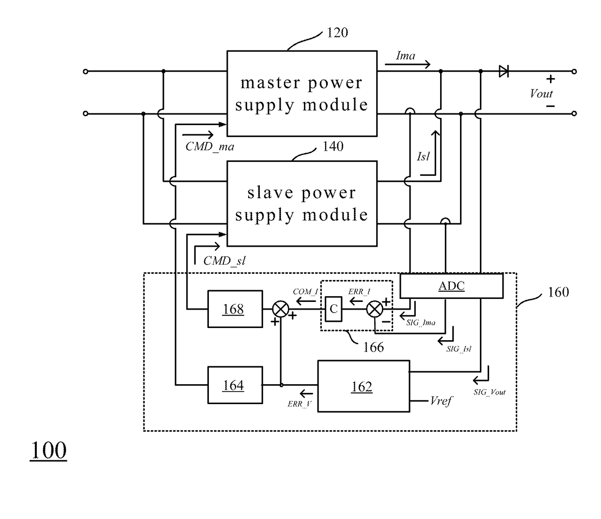
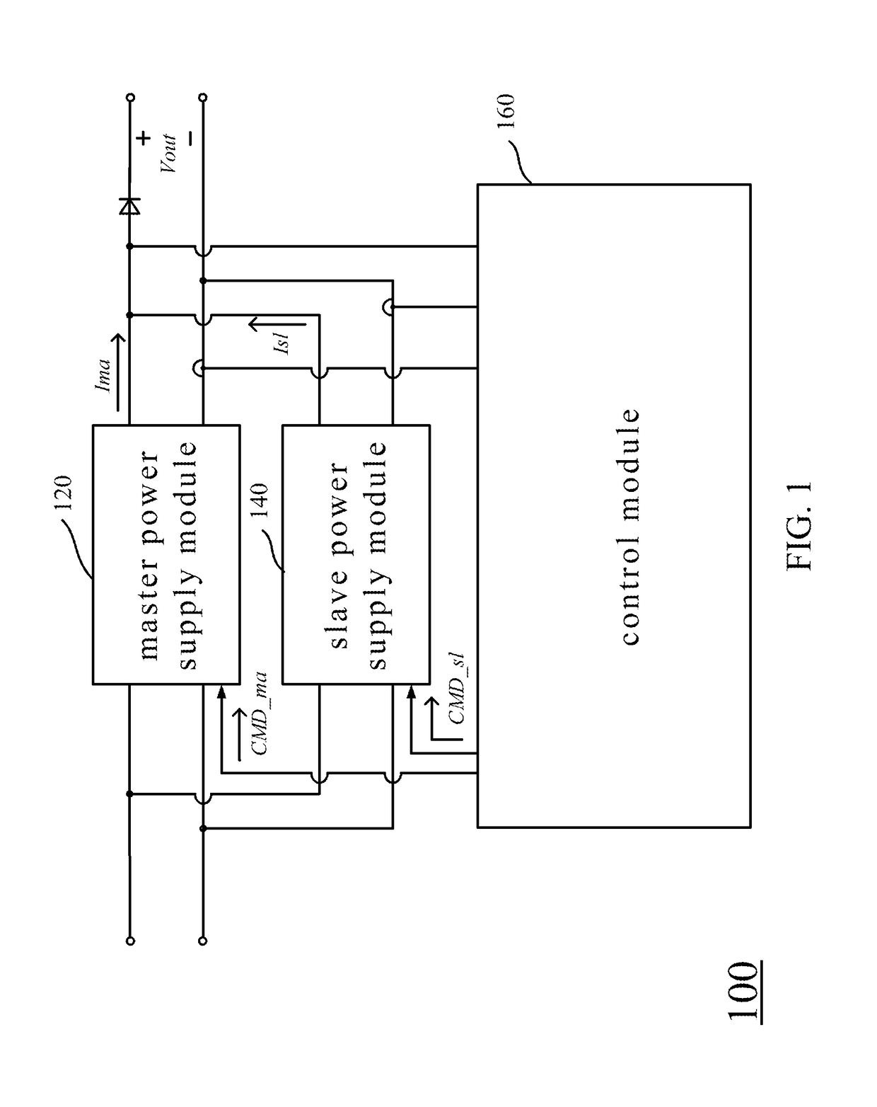
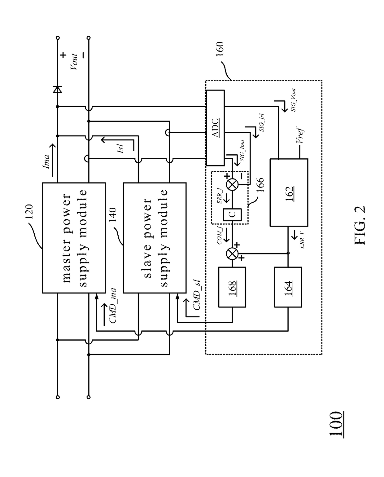
A power supply device includes a master power supply module, a slave power supply module and a control module. The master power supply module is configured to output a master output current and an output voltage according to a master control signal. The slave power supply module is electrically connected in parallel to the master power supply module and configured to output a slave output current and the output voltage according to a slave control signal. The control module is electrically connected to the master power supply module and the slave power supply module and configured to output the master control signal according to the output voltage, generate a current compensation signal according to the master output current and the slave output current, and output the slave control signal according to the output voltage and the current compensation signal which is based on the master output current.

Description

RELATED APPLICATIONS[0001]This application claims priority to China Application Serial Number 201510040507.4, filed Jan. 27, 2015, which is herein incorporated by reference.BACKGROUND[0002]1. Technical Field[0003]The present disclosure relates to a power supply device, and in particular, to a power supply device with current equalization.[0004]2. Description of Related Art[0005]With the extensive use of power supplies in servers and in the field of communications, in order to achieve the requirements of high efficiency, high power density, high reliability, and low cost, more and more power supplies adopt a modular design for varying power levels by connecting different numbers of power modules in parallel.[0006]However, when a power supply includes two or more power modules connected in parallel, the quality of the power supply will depend largely on whether the output currents of the power modules are equal. With existing current equalization approaches, such as the droop method a...

Claims


Application Information

Patent Timeline
Patent Type & Authority Patents(United States)
IPC IPC(8): H02M3/155H02M3/335H02M3/28H02M1/00
CPCH02M3/155H02M3/285H02M3/33576H02M2001/007H02M1/007
Inventor YIN, GUO-DONGWU, BENLIU, ZHI-WEI
Owner DELTA ELECTRONICS INC
Learn More