
Magnetic device for pivoting an arbor of a rotating member in a timepiece movement

a technology of rotating parts and magnetic devices, which is applied in the direction of magnetic bearings, instruments, and reliable timepiece mechanisms that operate in accordance, and can solve the problems of difficult control of positioning and intensity of magnetic fields on this scale, reducing dimensions, and reducing so as to reduce the risk of damaging the magnetic field produced by the magnet. , the effect of less restriction

Active Publication Date: 2017-03-28
MONTRES BREGUET
View PDF10 Cites 2 Cited by
  • Summary
  • Abstract
  • Description
  • Claims
  • Application Information

AI Technical Summary

Benefits of technology

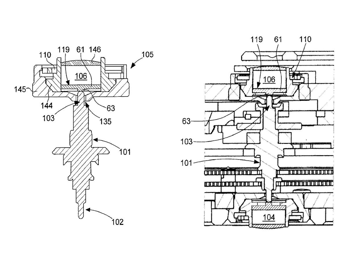
[0011]According to the invention, the endstone is made of a material with a high magnetic permeability and is arranged between the magnet and the pivot. In these conditions, it will be understood that, from a magnetic point of view, the endstone of the invention plays the part of a pole piece. Further, because in cross-section the dimensions of the pole piece are smaller than those of the magnet, the pole piece acts as a magnetic flux concentrator. As a result of this feature, the invention makes it possible to increase, on the one hand, the magnetic field intensity at the bearing surface of the endstone, and on the other hand, the radial gradient of the magnetic field. A first advantage of the invention is thus to increase the magnetic return force which acts radially on the pivot.
[0012]According to the invention, the endstone is arranged to be centred on the pivot axis. Further, as the endstone concentrates the magnetic field, the area where the magnetic field is most intense is also centred on pivot axis. This is the case regardless of the assembly tolerances of the magnet. One advantage of this feature is that, instead of driving in the magnet, it is possible to use a less precise but also less restrictive method, such as adhesive bonding for example. The risk of damaging the magnetic field produced by the magnet is thus reduced. It will also be understood that a second advantage of the aforementioned feature is that the pivot is centred with improved precision regardless of any magnetic defects in the magnet.
[0013]According to the invention, the same component plays the part of an endstone and that of a magnetic flux concentrator, and also that of the magnetic structure for centring the magnetic arbor, i.e. for aligning the arbor on the pivot axis provided. A third advantage of the invention is therefore that it concentrates the magnetic flux while correctly centring the pivot on the pivot axis provided, without increasing the dimensions of the pivoting device. Further, it will be understood that in reducing the number of components, the invention makes it possible to simplify the design and reduce costs.

Problems solved by technology

Producing reliable timepiece mechanisms that operate in accordance with the principles described above represents a significant technical challenge, because of the extremely reduced dimensions and high spatial precision required to perform chronometric functions with precision.
The positioning and intensity of magnetic fields on this scale is thus difficult to control.
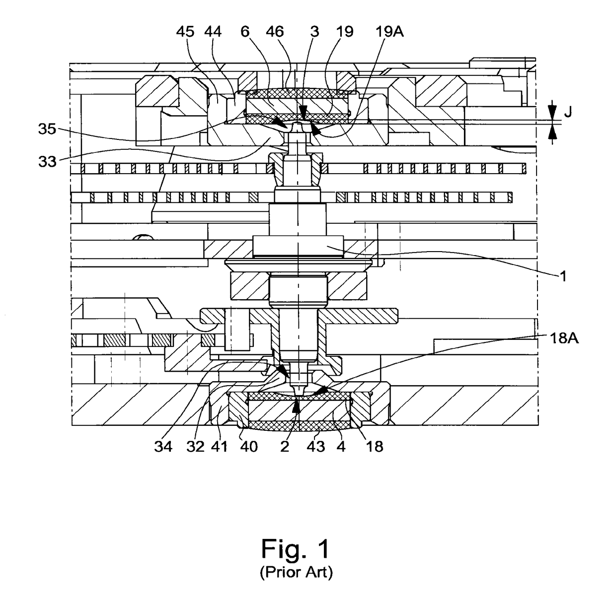
Another drawback of the type of pivoting devices shown in FIG. 1 is related to the presence of the jewel cap (respectively 18 and 19) between the magnet and the pivot.

Method used


Image

  • Magnetic device for pivoting an arbor of a rotating member in a timepiece movement
  • Magnetic device for pivoting an arbor of a rotating member in a timepiece movement
  • Magnetic device for pivoting an arbor of a rotating member in a timepiece movement

Examples


first embodiment

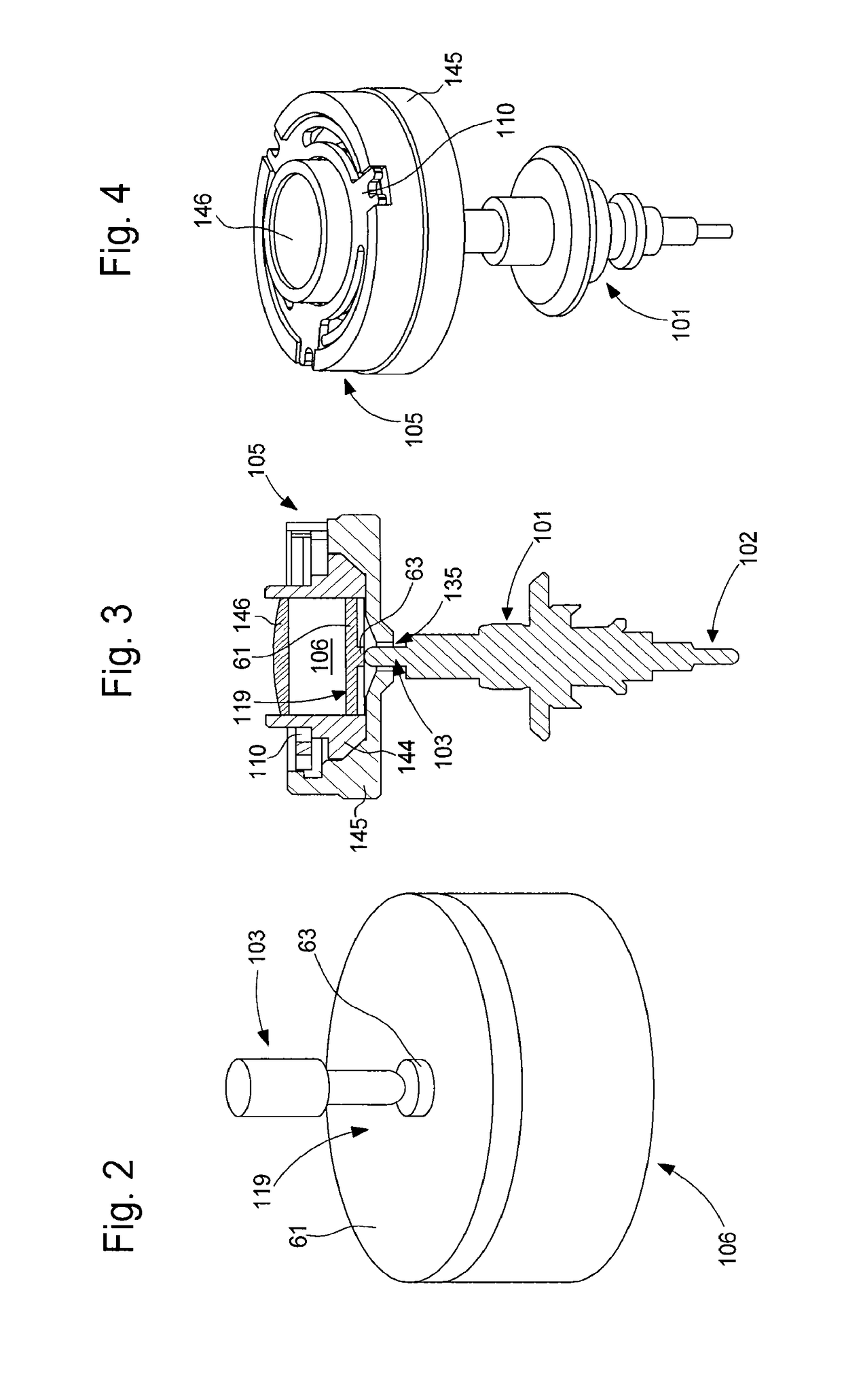
[0030]Referring now more specifically to FIGS. 3, 4 and 5, a design variant will now be described in more detail for the invention. This embodiment corresponds to an anti-shock pivoting device.

[0031]The illustrated pivoting device includes an arbor 101 whose ends form two pivots, respectively referenced 102 and 103. Pivot 103 is made of a magnetic material. The Figures also show a first bearing 105 including a magnet 105, arranged to support and guide in rotation pivot 103, and a second bearing including a magnet 104 similar to the first bearing.

[0032]Hereinafter there will be described only the first bearing, which includes a setting 144, a bearing jewel 146 abutting against the bottom of the setting, a permanent magnet 106 mounted in the setting against the bearing jewel, and a pole structure 119 inserted between the magnet and the opening of the setting. In the illustrated example, bearing jewel 146 has no technical function other than closing the bottom of the setting and acting...

third embodiment

[0039]It will be understood that frame 361 and arms 365 can be formed of the same material as the actual endstone. In such case, the presence of an annular space between the endstone and the frame prevents the pole structure forming a shield returning the field lines back towards the other pole of the magnet. Thus, the third embodiment makes it possible to have a thicker, and thus more solid frame, even if it is made of the same material as the endstone. Alternatively, frame 361 and arms 365 may be made of a different material from that forming the endstone.

[0040]Referring more specifically now to FIG. 8A, it can be seen that the pole structure shown includes a frame 371 and an endstone 73 connected to each other by four connecting elements 375. As can be seen, the connecting elements illustrated are in the form of small bars bent in an arc of a circle. It will be understood that, in the variant shown, the curvature of small bars 375 forms a resilient connection between the central ...

fourth embodiment

[0042]FIG. 9 is a partial longitudinal cross-sectional view illustrating a bearing of a pivoting device corresponding to the invention. One peculiarity of this latter embodiment is that the pole structure does not have a peripheral frame but is limited to an endstone whose dimensions, in cross-section to the pivot axis, are smaller than those of the magnet. In the Figure there is seen a magnet 406 and an endstone 463 which is bonded directly onto the magnet. The endstone is formed, according to the invention, of a magnetic material having good tribological properties.


PUM


Abstract

The device for pivoting an arbor of a rotating member, on a determined pivot axis, inside a timepiece movement includes at least one magnetic bearing including a magnet which exerts a force of attraction on a pivot made of magnetic material, of the arbor, and an endstone arranged between the magnet and the pivot, the endstone being formed of a material having a hardness greater than 500 HV and a friction coefficient less than or substantially equal to 0.1 with the material of which the pivot is made. The material forming the endstone has a high magnetic permeability and the endstone has, in cross-section to the pivot axis, smaller dimensions than those of the magnet, said endstone being arranged in the timepiece movement to be centred on the determined pivot axis.

Description

[0001]This application claims priority from European Patent Application No. 15172405.1 filed on Jun. 16, 2015, the entire disclosure of which is hereby incorporated herein by reference.FIELD OF THE INVENTION[0002]The present invention concerns a timepiece assembly comprising an arbor of a rotating member and a device for pivoting the arbor about a determined axis inside a timepiece movement, including at least one magnetic bearing comprising a magnet which exerts a force of attraction on a pivot, made of magnetic material, of the arbor, and an endstone arranged between the magnet and the pivot. The present invention more specifically concerns such a device wherein the friction coefficient between the endstone and the pivot is less than or substantially equal to 0.1 and wherein the material of which the endstone is formed has a hardness greater than 500 HV.PRIOR ART[0003]The use of permanent magnets in rotating members of timepiece movements is potentially advantageous, especially be...

Claims


Application Information

Patent Timeline
Patent Type & Authority Patents(United States)
IPC IPC(8): G04B31/00G04B31/012F16C32/04
CPCG04B31/012F16C32/041F16C32/0408G04B31/00G04B17/32G04B31/02F16C32/0421F16C17/08F16C25/045F16C27/02F16C32/0417F16C33/043F16C2206/82F16C2370/00G04B31/004G04B31/04
Inventor MARECHAL, SYLVAINLEGERET, BENOIT
Owner MONTRES BREGUET
Learn More