
Systems and methods for time/frequency indexed pulse calibrations for vector network analyzers

a vector network analyzer and time/frequency index technology, applied in the direction of resistance/reactance/impedence, instruments, measurement devices, etc., can solve the problems of instrument-related stimulus pulsing effects that are not commonly accounted for, and the stimulus modulation is defectiv

Active Publication Date: 2017-03-28
ANRITSU CO
View PDF2 Cites 20 Cited by
  • Summary
  • Abstract
  • Description
  • Claims
  • Application Information

AI Technical Summary

Benefits of technology

The patent describes a method and system for measuring scattering parameters in a device under test (DUT) using a vector network analyzer (VNA). The method includes calibrating the VNA to correct for setup defects and mapping error terms based on time indices. A test signal is transmitted to the DUT, and the resulting measurements are time-aligned with the mapped error terms. The system includes a pulse modulator for transmitting a RF pulse profile test signal to the DUT and obtaining measurements of electrical performance. The generated corrections are time-aligned with the pulses in the measurements. The technical effect of the patent is to provide a more accurate and reliable method for measuring scattering parameters in a DUT.

Problems solved by technology

In a pulsed measurements system, when a stimulus is pulsed there are defects in the stimulus modulation that may be undesirably introduced by the pulse modulator (e.g., overshoot).
These defects are in addition to defects attributable to the DUT.
Generally, it is assumed that any instrument-related stimulus pulsing effects have settled out prior to measurements being made either because it is difficult or there is not enough measurement time resolution to allow those effects to be noticed.
Therefore, instrument-related stimulus pulsing effects are not commonly accounted for during calibration.

Method used


Image

  • Systems and methods for time/frequency indexed pulse calibrations for vector network analyzers
  • Systems and methods for time/frequency indexed pulse calibrations for vector network analyzers
  • Systems and methods for time/frequency indexed pulse calibrations for vector network analyzers

Examples


Embodiment Construction

[0016]The following description is of the best modes presently contemplated for practicing various embodiments of the present invention. The description is not to be taken in a limiting sense but is made merely for the purpose of describing the general principles of the invention. The scope of the invention should be ascertained with reference to the claims.

[0017]It would be apparent to one of skill in the art that the present invention, as described below, may be implemented in many different embodiments of hardware, software, firmware, and / or the entities illustrated in the figures. Any actual software, firmware and / or hardware described herein is not limiting of the present invention. Thus, the operation and behavior of the present invention will be described with the understanding that modifications and variations of the embodiments are possible, given the level of detail presented herein.

[0018]As measurement resolution improves technologically, ignoring instrument-related stimu...


PUM


Abstract

A method for measuring scattering parameters in a device under test (DUT) using a vector network analyzer (VNA), includes calibrating the VNA to generate corrections for deterministic setup defects and mapping a plurality of error terms based on a plurality of time indices, wherein each time indicia is associated with an error term. A test signal is transmitted to the DUT to obtain a measurement signal from the DUT in response to the test signal. The generated corrections to obtained measurements are time aligned based on the mapped error terms.

Description

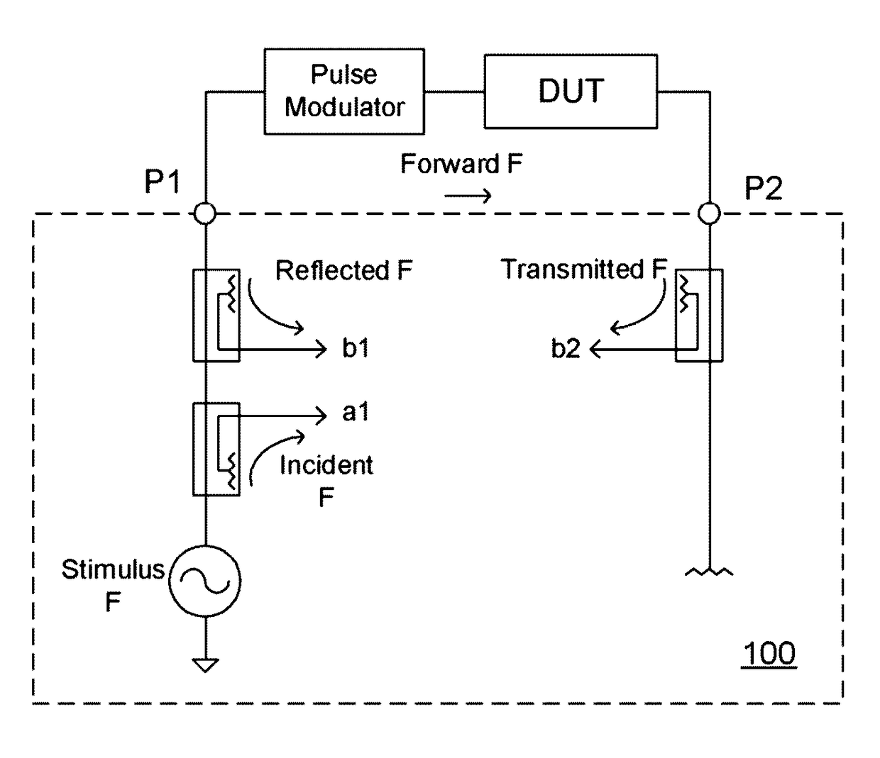
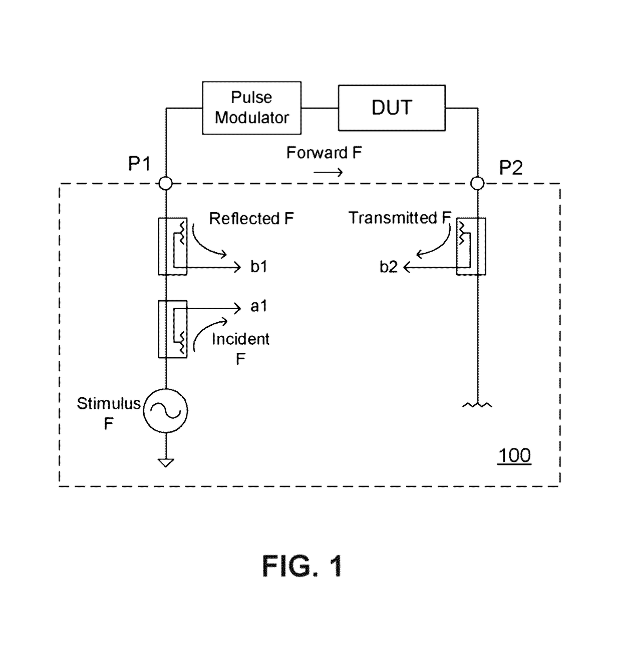
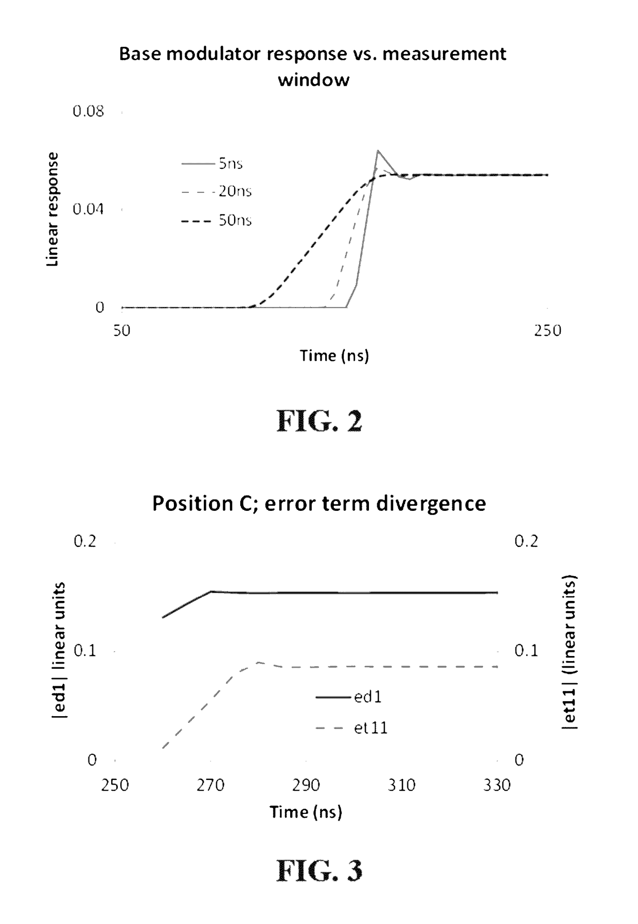
CLAIM OF PRIORITY[0001]This application claims the benefit of priority to U.S. Provisional Application titled “SYSTEMS AND METHODS FOR TIME / FREQUENCY INDEXED PULSE CALIBRATIONS FOR VECTOR NETWORK ANALYZERS”, Application No. 61 / 793,702, filed Mar. 15, 2013, which application is herein incorporated by referenceTECHNICAL BACKGROUND[0002]The present invention relates to vector network analyzers and pulse profiling measurements using vector network analyzers.BACKGROUND[0003]Radio frequency (RF) pulse profiling vector network analyzer (VNA) measurements are commonly used to evaluate a response of a device under test (DUT) to a pulse stimulus. FIG. 1 illustrates an exemplary set-up for measuring a two-port DUT, with a pulse modulator arranged between a VNA 100 and the DUT. DUT response details often evaluated in magnitude and phase include overshoot, droop, ringing, etc. FIG. 2 illustrates an example of a linear response of a base modulator. The measurement window includes a leading edge o...

Claims


Application Information

Patent Timeline
Patent Type & Authority Patents(United States)
IPC IPC(8): G01R35/00G01R31/00
CPCG01R35/005G01R27/32
Inventor MARTENS, JON S.
Owner ANRITSU CO
Learn More