
Pressure driven microfluidic injection for chemical separations

a microfluidic injection and chemical separation technology, applied in particle separator tube details, instruments, laboratory glassware, etc., can solve the problems of ineffective use of some on-device sample focusing methods and injection bias of microfluidic methods that employ electrokinetic flow of samples into separation channels

Active Publication Date: 2017-03-28
THE UNIV OF NORTH CAROLINA AT CHAPEL HILL
View PDF26 Cites 12 Cited by
  • Summary
  • Abstract
  • Description
  • Claims
  • Application Information

AI Technical Summary

Benefits of technology

The invention provides methods for injecting samples into a separation system without bias, allowing for precise volumes of sample to be delivered. This results in consistent peak areas in the electropherograms, improving the accuracy of the analysis.

Problems solved by technology

Conventional microfluidic methods that employ electrokinetic flow of sample into the separation channel are subject to injection bias and cannot effectively be used for some on-device sample focusing methods.

Method used


Image

  • Pressure driven microfluidic injection for chemical separations
  • Pressure driven microfluidic injection for chemical separations
  • Pressure driven microfluidic injection for chemical separations

Examples


examples

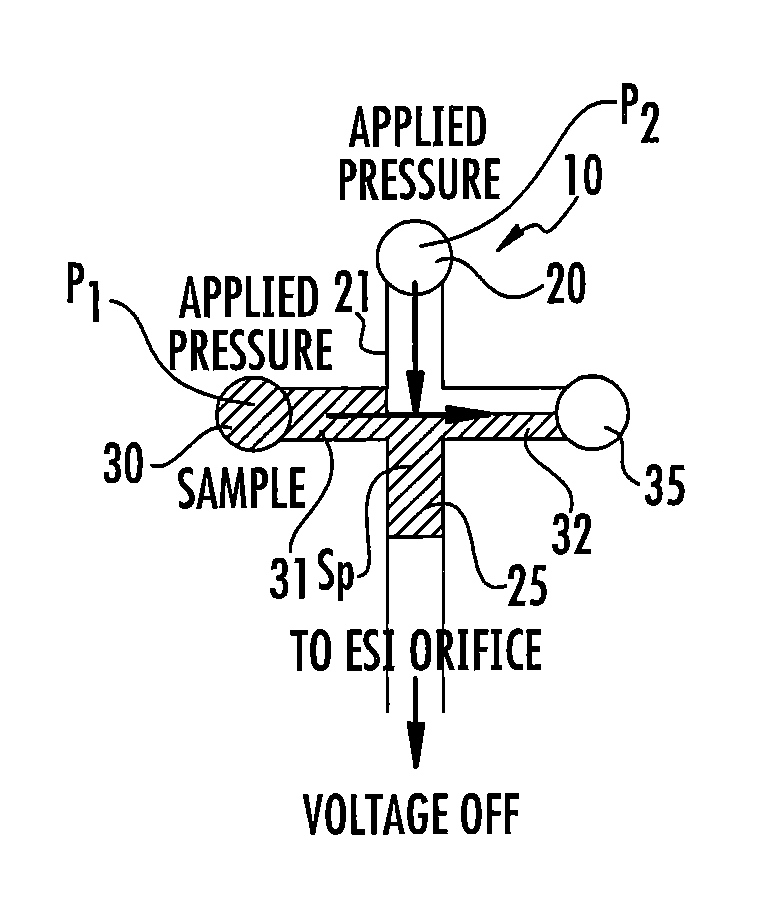
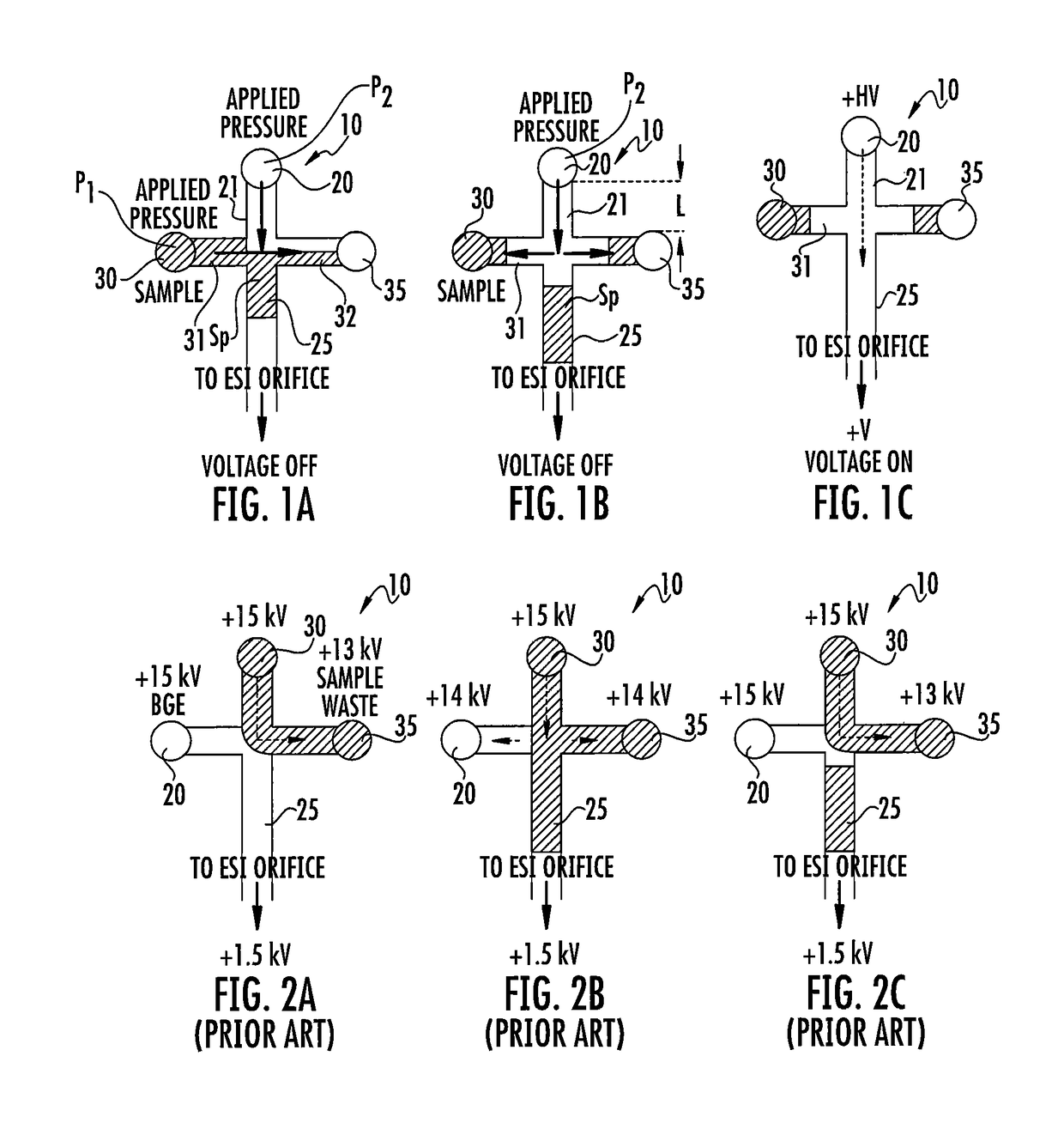
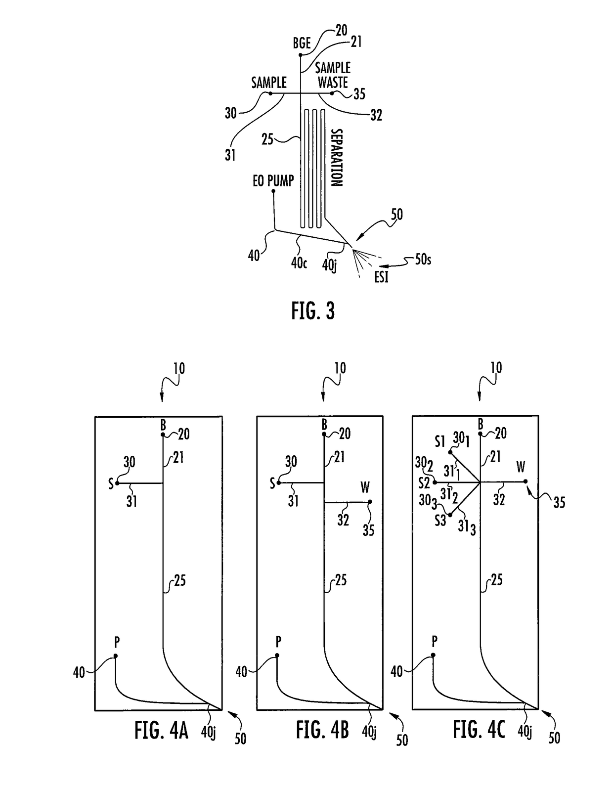
[0124]Microchip CE with integrated ESI for MS detection was used for the analysis of amino acids. The new pressure-driven injection method was compared to the commonly used electrokinetic (EK) gate method (using the methodology described in FIGS. 1A-1C and 2A-2C) using the microfluidic device shown in FIG. 3. This type of microchip CE-ESI device has been described previously and is commonly used in lab settings. For all of the data presented here, the sample contained a 10 μM mixture of the 20 essential amino acids. The salt content of the samples was varied to illustrate the superior salt tolerance of the new injection method and also to illustrate the phenomenon of transient isotachophoresis (tITP) that is allowed by the new pressure-driven injection method. All separations were performed with a separation field strength of approximately 1000 V / cm with a background electrolyte (BGE) of 50% methanol, 2% formic acid (pH 2.2). Computer control of voltages applied to the microfluidic ...


PUM

PropertyMeasurementUnit
pressuresaaaaaaaaaa
pressuresaaaaaaaaaa
pressureaaaaaaaaaa

Abstract

Methods that allow independently applied pressures to a BGE reservoir and a sample reservoir for pressure-driven injection that can inject a discrete sample plug into a separation channel that does not require voltage applied to the sample reservoir and can allow for in-channel focusing methods to be used. The methods are particularly suitable for use with a mass spectrometer.

Description

RELATED APPLICATIONS[0001]This application is a continuation application of U.S. patent application Ser. No. 14 / 708,906, filed May 11, 2015, the contents of which are hereby incorporated by reference as if recited in full herein.STATEMENT OF FEDERAL SUPPORT[0002]This invention was made with government support under Grant No. GM066018 awarded by the National Institutes of Health and Grant No. W911NF-12-1-0539 awarded by the United States Army. The United States government has certain rights in the invention.FIELD OF THE INVENTION[0003]This invention is related to microfluidic sample processing that may be particularly suitable for electrospray ionization and / or sample processing systems that interface with mass spectrometers.BACKGROUND OF THE INVENTION[0004]Electrospray ionization (“ESI”) is an important technique for the analysis of biological materials contained in solution by mass spectrometry. See, e.g., Cole, R. B. Electrospray Ionization Mass Spectrometry: Fundamentals, Instrum...

Claims


Application Information

Patent Timeline
Patent Type & Authority Patents(United States)
IPC IPC(8): G01N27/447H01J49/16B01L3/00G01N30/72
CPCG01N27/44743B01L3/50273G01N27/44791H01J49/165B01L2300/0864B01L2400/049B01L2400/0418B01L2400/0421B01L2400/0487B01L2400/0622B01L2400/0666G01N30/7266G01N27/4473B05B5/00G01N2030/167G01N30/16B01L2200/0605B01L2300/0816B01L2400/0694H01J49/167
Inventor MELLORS, JOHN SCOTTREDMAN, ERIN ANNERAMSEY, JOHN MICHAEL
Owner THE UNIV OF NORTH CAROLINA AT CHAPEL HILL
Learn More