
Percutaneous rod-to-rod cross connector

a cross-connector and percutaneous technology, applied in the field of minimally invasive surgical screw system, can solve the problems of limiting the range of spinal pathologies, increasing the likelihood that surgery may be needed to correct one or more spinal pathologies, and spinal pathologies

Active Publication Date: 2017-03-28
NEUROVENT
View PDF82 Cites 11 Cited by
  • Summary
  • Abstract
  • Description
  • Claims
  • Application Information

AI Technical Summary

Benefits of technology

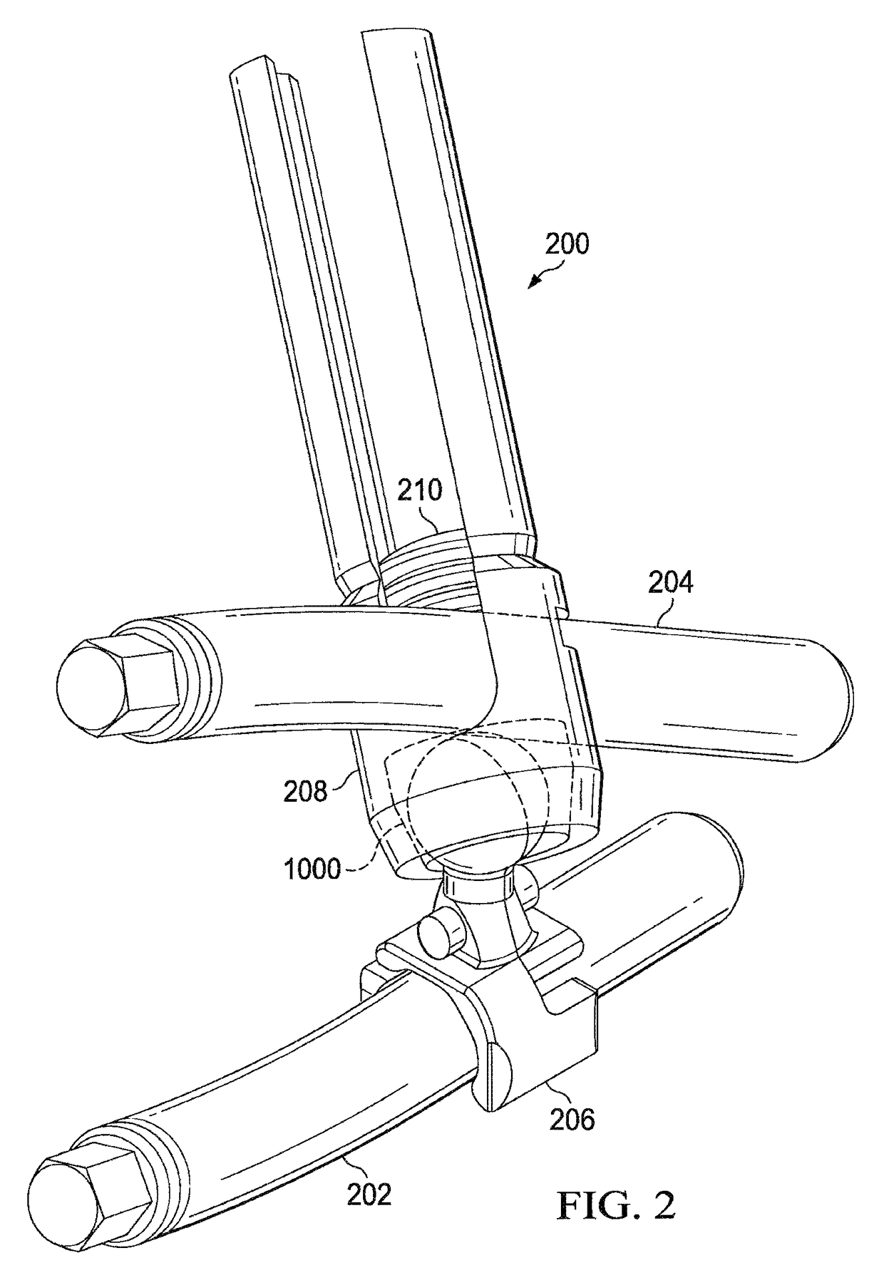
The surgical screw system described in this patent is a modular system for connecting rods used in spine surgery. The system allows for percutaneous delivery of the implantation rods and is designed to reduce the invasiveness and risks of spine surgery. The system includes a rod attachment device with a split-orbital head and a rod attachment claw, as well as a first and second u-shaped body for receiving a cross-connecting rod and a retaining ring for aligning the split-orbital head. The system also includes a compression element for driving the cross-connecting rod against the retaining ring to bring the split-orbital head into substantial circumferential alignment. The technical effects of this system include improved operational precision, reduced surgery duration and risk, and improved patient outcomes.

Problems solved by technology

With its complex nature, however, there is also an increased likelihood that surgery may be needed to correct one or more spinal pathologies.
Genetic or developmental irregularities, trauma, chronic stress, tumors and disease can result in spinal pathologies that either limit this range of motion or that threaten critical elements of the nervous system housed within the spinal column.
The orientation of each of these rods, however, are often limited by the alignment of the one or more screws they are affixed to.

Method used


Image

  • Percutaneous rod-to-rod cross connector
  • Percutaneous rod-to-rod cross connector
  • Percutaneous rod-to-rod cross connector

Examples


Embodiment Construction

[0038]For purposes of describing and claiming the present disclosure, the term “interference fit” is intended to refer to physical contact between two or more components and may include a slip fit, a ball-joint fit, or similar fit between two or more components. In addition, the terms “modular” and “modularity” are intended to refer to the interactions between the various components of the rod-to-rod cross connecting system described herein. Various combinations of individual components may come pre-assembled together, or each component may be assembled together component-by-component during surgery.

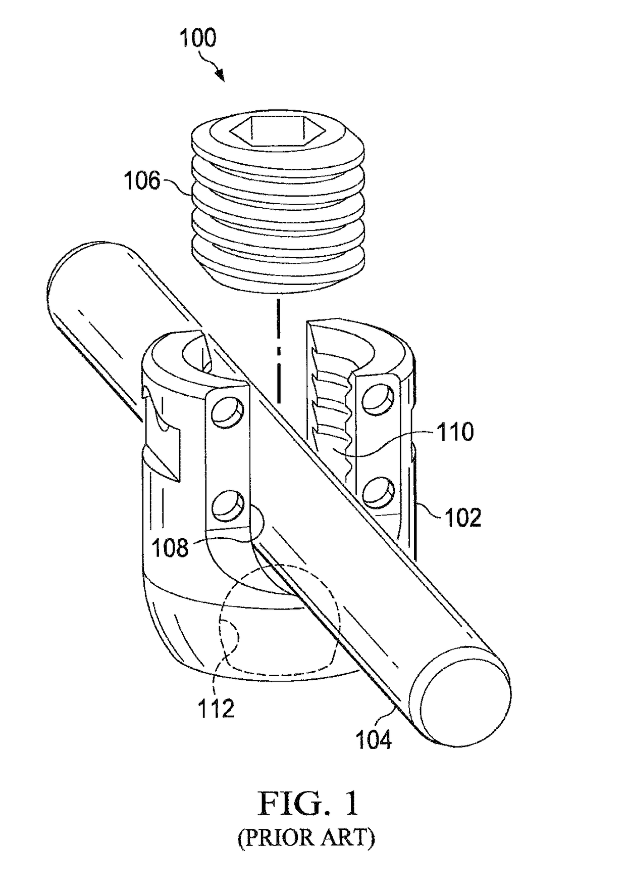
[0039]FIG. 1 depicts a prior rut connection system 100 for connecting a fastener element (e.g., a pedicle screw, not shown) relative to a rod 104 for vertebral fixation. Connection system 100 may comprise a U-shaped body 102, the rod 104, and a compression element 106. The rod 104 may be shaped to fit within the U-shaped body 102 at a rod receiving channel 108 with a slip fit. After the ...


PUM


Abstract

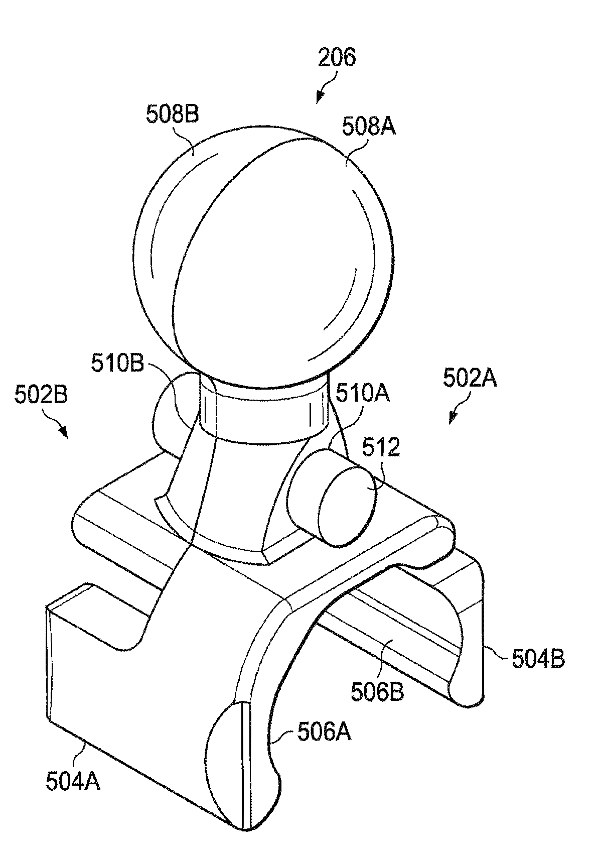
A percutaneous cross connector system for use with implantation rods comprising a rod attachment device comprising a first jaw portion and a second jaw portion. The first jaw portion comprises a first concave surface to engage with a surface of a rod, a first biasing member, and a first pivoting mechanism. The second jaw portion comprises a second concave surface to engage with an opposite surface of the rod from the first jaw portion, a second pivoting mechanism, a second biasing surface, and a second locking surface. The first and second jaw portions can be mated so that the first and second concave surfaces are positioned on opposite sides of the rod, the first and second pivoting mechanisms are aligned to pivot on a common axis, and the first biasing member is engaged against the second biasing surface to drive the second jaw portion against the rod.

Description

[0001]This is a Continuation of patent application Ser. No. 14 / 941,135 filed Nov. 13, 2015.FIELD OF THE INVENTION[0002]The present disclosure relates to a minimally invasive surgical (“MIS”) screw system comprising modular and / or pre-assembled rod-to-rod cross connectors and / or ipsilateral connectors for use with implantation rods, and related methods of using a MIS or traditional open screw system comprising modular and / or pre-assembled rod-to-rod cross connectors and / or ipsilateral connectors with implantation rods. In an embodiment, the system may allow true percutaneous delivery through the spinous ligament.BACKGROUND OF THE INVENTION[0003]The spinal column of bones is highly complex anatomical structure that includes over 20 bones coupled to one another, housing and protecting critical elements of the nervous system having innumerable peripheral nerves and circulatory bodies in close proximity. Despite its complexity, the spine is a highly flexible structure, capable of a high ...

Claims


Application Information

Patent Timeline
IPC IPC(8): A61B17/70
CPCA61B17/7043A61B17/7083A61B17/7032A61B17/7049A61B2090/037
Inventor FRANKEL, BRUCE
Owner NEUROVENT
Learn More