Hand blender with a built-in 2-speed gearbox
a technology of hand blender and gearbox, which is applied in the field of hand blender with a built-in 2speed gearbox, can solve the problems of inability to meet the demand for stirring different types of food, inability to achieve the conventional hand-held blender, and unstable transmission, so as to achieve better adaptability, better flexibility, and different stirring speeds
- Summary
- Abstract
- Description
- Claims
- Application Information
AI Technical Summary
Benefits of technology
Problems solved by technology
Method used
Image
Examples
embodiment i
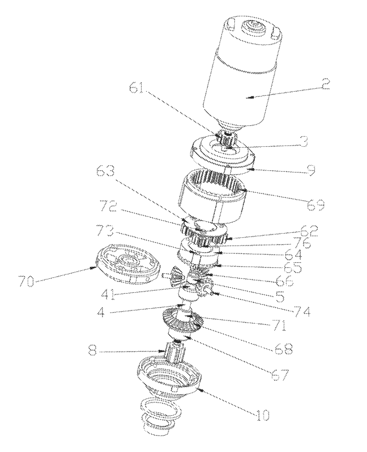
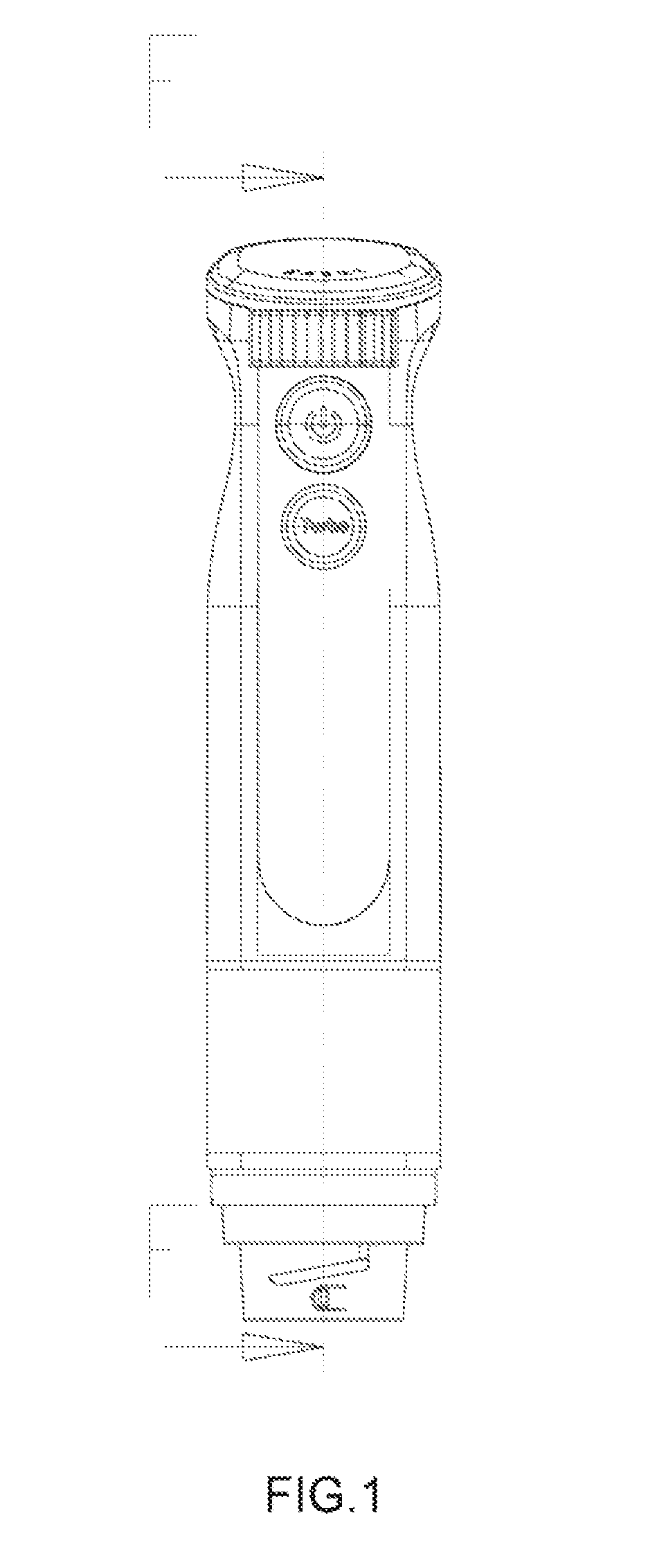
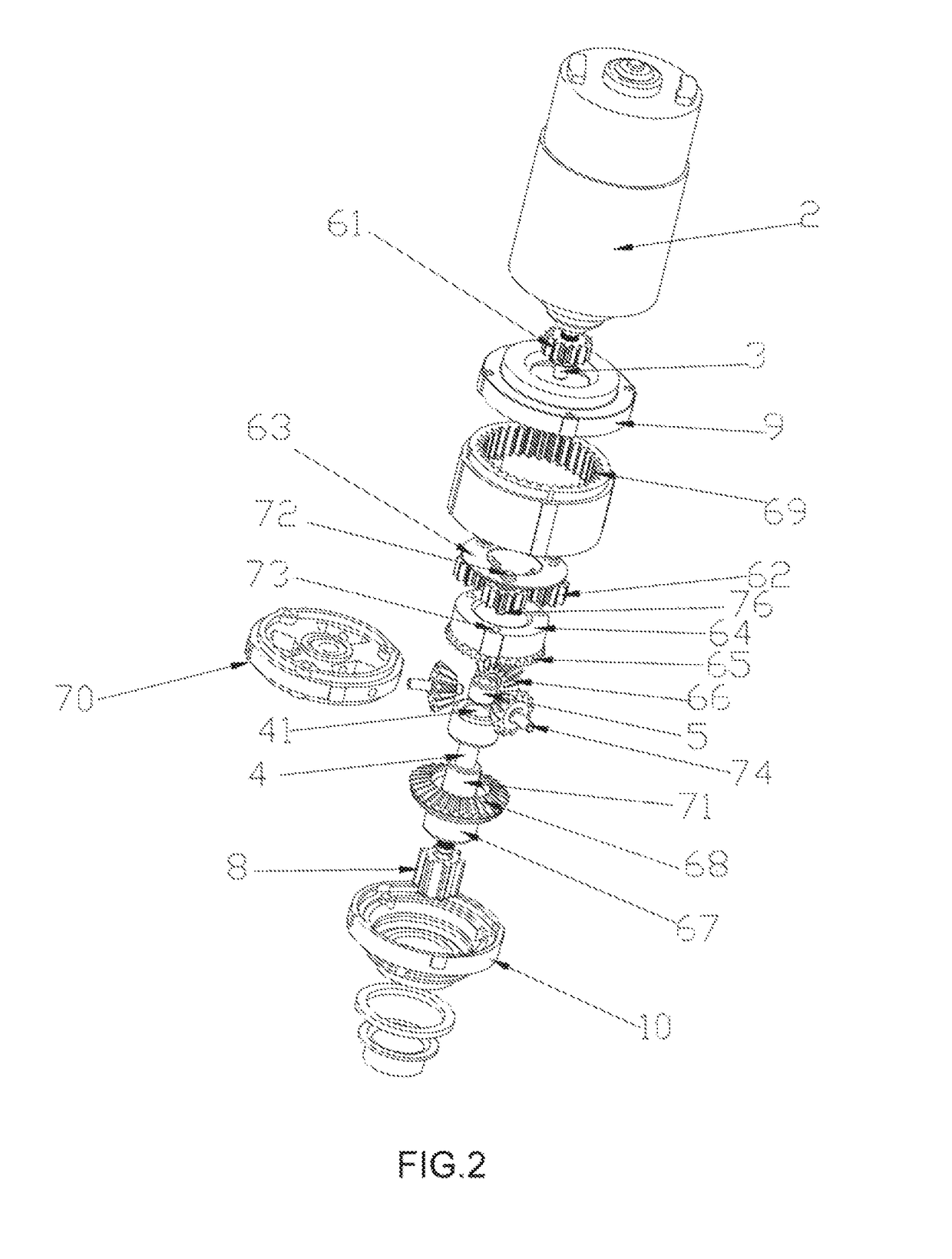
[0040]As shown in FIGS. 1-3, a hand blender with a built-in 2-speed gearbox according to a first embodiment of the present invention includes a housing 1, a motor 2 arranged in the housing 1, an input shaft 3 synchronously rotatable with a rotor of the motor 2, an output shaft 4 for outputting power to a stirring tool, an upper end cover 9 configured in the housing under the motor, a connector 8, a lower end cover 10 arranged in the housing above the connector, a constant transmission assembly 5, and a differential transmission assembly 6. The constant transmission assembly 5 and the differential transmission assembly 6 are arranged between the input shaft 3 and the output shaft 4, and are configured to drive the output shaft 4 to rotate clockwise whenever the motor rotates clockwise or anticlockwise. The connector 8 is set at a lower end of the output shaft 4 and engages with the stirring tool. The output shaft and the input shaft are coaxially arranged. The constant transmission a...
embodiment ii
[0044]As shown in FIG. 4, the structure of the hand blender with a built-in 2-speed gearbox revealed in this embodiment is similar to the structure disclosed in embodiment I, the difference is that, bearing one-way bearing II 75 is arranged between the input shaft 3 and the sun gear 61, and is locked to rotate anticlockwise. The one-way bearing II 71 disclosed in embodiment I is omitted and is not arranged between the lower transmuting turntable 67 and the output shaft 4, the lower transmitting turntable rigidly connects with the output shaft. When the input shaft 3 rotates clockwise, the one-way bearing II 75 rotates freely, the driving force of the input shaft 3 cannot transmit to the differential transmission assembly 6, power is transmitted to the output shaft 4 via the one bearing I, the output shaft 4 rotates clockwise in a transmission ratio of 1.1. The output shaft 4 drives the differential transmission assembly 6 rotating through the lower transmitting turntable 67, power i...
embodiment iii
[0046]As shown in FIG. 5, the structure of the hand blender with a built-in 2-speed gearbox in this embodiment is similar to the structure of that in the embodiment I, the difference is that, a one-way bearing II 75 is arranged between the input shaft and the sun gear, and another one-way bearing II 71 is arranged between the lower transmitting turntable and the output shaft. The one way bearing II 75 is locked when driven anticlockwise, when the input shaft 3 rotates clockwise, power is transmitted to the output shaft 4 through the one-way bearing, the output shaft 4 drives a stirring rod connected with the connector 8 to rotate, the connector 8 can connect different tools detachably such as a stirring tool, a cutting tool, etc. At this moment, the differential transmission assembly 6 rotates freely because the one-way bearing II 75 is locked to rotate anticlockwise, the driving force of the input shaft 3 is not transmitted to the differential transmission assembly 6, therefore the...
PUM
 Abstract
Description
Claims
Application Information
 - R&D Engineer
- R&D Manager
- IP Professional
- Industry Leading Data Capabilities
- Powerful AI technology
- Patent DNA Extraction
Browse by: Latest US Patents, China's latest patents, Technical Efficacy Thesaurus, Application Domain, Technology Topic, Popular Technical Reports.
© 2024 PatSnap. All rights reserved.Legal|Privacy policy|Modern Slavery Act Transparency Statement|Sitemap|About US| Contact US: help@patsnap.com


