Agricultural implement actuator sensor projection

a technology for actuators and agricultural implements, applied in agricultural tools and machines, adjusting devices, agricultural machines, etc., can solve the problems of reducing the efficiency and speed with which the particular task is accomplished, the difficulty of having a level positioning of the implement, and the criticality of having a uniform and level tool contact with the soil, etc., to achieve the effect of being more robust and effectiv

Active Publication Date: 2017-03-07
CNH IND CANADA
View PDF19 Cites 13 Cited by
  • Summary
  • Abstract
  • Description
  • Claims
  • Application Information

AI Technical Summary

Benefits of technology

[0009]An advantage of the present invention is a more robust and effective sensor used in the synchronization of multiple sections of a farm implement.
[0010]In one form, the invention is an actuator for a tillage machine, the actuator including an actuator housing forming a cylinder and a piston displaceable in that cylinder in response to hydraulic fluid. An output shaft is connected to the piston and extends outside of the actuator housing to provide a variable extension in response to hydraulic fluid inputs. The shaft is encoded with information reflecting the displacement of the output shaft relative to the actuator housing. A sensor is mounted in the housing and has an end face positioned for reading the encoded information. A sensor support surrounds the sensor with the sensor being counter sunk in the sensor support by the amount of clearance necessary between the end face of the sensor and the shaft for sensing of the encoded material. The sensor support is adjustably mounted in the actuator housing to abut the output shaft.
[0011]In another form, the invention is an agricultural implement spanning a lateral distance relative to a forward direction over soil, with the implement including a plurality of carrier frames, each for supporting a plurality of soil engaging tools. At least one supporting element is carried by each carrier frame for variably positioning the carrier frame relative to the soil. An actuator is connected between each supporting element and the respective carrier frame for varying the position of the respective carrier frame relative to the soil, the actuator including a housing forming an internal cylinder and a piston displaceable in the cylinder in response to hydraulic fluid input. An output shaft is connected to the piston and extends outside of the actuator housing to connect between the carrier frame and the supporting element to vary the position of the carrier frame relative to the soil. The output shaft is encoded with information reflecting the displacement of the output shaft relative to the actuator housing. A sensor is mounted in the housing and has an end face for reading the encoded information. A sensor support surrounds the sensor with the sensor being counter sunk in the sensor support by the amount of clearance necessary for sensing of the encoded material on the output shaft with the sensor support being adjustably mounted to abut the output shaft.

Problems solved by technology

When the span increases to realize greater efficiency and speed, the criteria of having a uniform and level tool contact with the soil becomes extremely critical.
The need to have a level positioning of the implement is made more challenging with the use of hydraulic actuators which control the depth of penetration of the disk blades or other tools.
However, this adds an additional step to the operation, particularly in the field, thereby decreasing the efficiency and speed with which the particular task is accomplished.
In the agricultural environment, the positioning of the sensor is a problem because the current practice of inserting the sensor until contact with the shaft and then backing it off may result in alteration of the sensor signal.

Method used


Image

  • Agricultural implement actuator sensor projection
  • Agricultural implement actuator sensor projection
  • Agricultural implement actuator sensor projection

Examples


Embodiment Construction

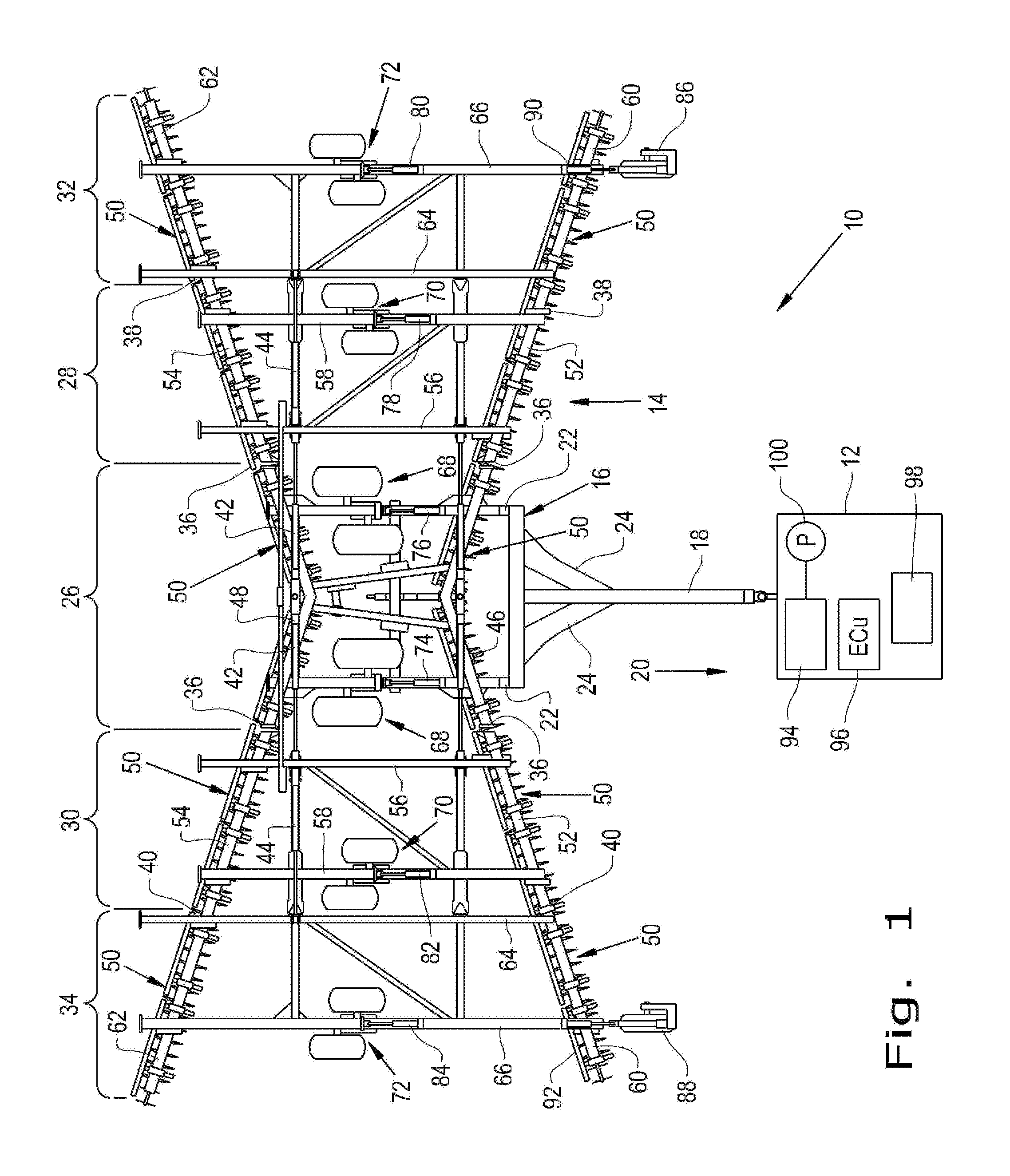
[0020]Referring now to the drawings, and more particularly to FIG. 1, there is shown a tillage apparatus 10 which generally includes a tractor 12 shown schematically and an agricultural tillage implement 14 for tilling the soil prior to seeding. It should be noted that many different tools may be employed with the tillage implement 14 beyond the embodiment shown.

[0021]Agricultural tillage implement 14 is configured as a multi-section field disk ripper 14, and includes a carriage frame assembly 16. Carriage frame assembly 16 is the section that is directly towed by a traction unit, such as agricultural tractor 12. Carriage frame assembly 16 includes a pull hitch 18 generally extending in a travel direction 20, and forward and aft oriented carrier frame members 22 which are coupled with and extend from pull hitch 18. Reinforcing gusset plates 24 may be used to strengthen the connection between pull hitch 18 and carrier frame members 22.

[0022]The tillage implement 14 has a center secti...


PUM


Abstract

A tillage implement spanning a lateral distance relative to a forward direction and having a plurality of carrier frames, each for supporting a plurality of soil engaging tools. A pivoting wheel assembly positions the carrier frames at a variable distance from the soil and an actuator is connected between the carrier frame and each support wheel assembly to vary the height of the carrier frame. The actuator has a sensor for generating a signal reflecting the displacement of the actuator. The sensor element is mounted in an adjustable sensor support and countersunk by the required clearance between the sensor element and encoded information on the output shaft so that the sensor support may be adjusted to abut the shaft and accurately position the sensor element.

Description

CROSS REFERENCE TO RELATED APPLICATIONS[0001]This is a non-provisional application based upon U.S. provisional patent application Ser. No. 61 / 914,566, entitled “AGRICULTURAL IMPLEMENT ACTUATOR SENSOR PROTECTION”, filed Dec. 11, 2013, which is incorporated herein by reference.BACKGROUND OF THE INVENTION[0002]1. Field of the Invention[0003]The present invention relates to agricultural implements, and, more particularly, sensors for use with actuators in such implements.[0004]2. Description of the Related Art[0005]In the continuing quest for providing greater efficiency in the operation of farm implements, machines have been constructed to have ever increasing lateral spans relative to a tractor or central unit propelling the unit over a field. When the span increases to realize greater efficiency and speed, the criteria of having a uniform and level tool contact with the soil becomes extremely critical. Equipment with significant lateral spans has many different joints and is usually ...

Claims


Application Information

Patent Timeline
Patent Type & Authority Patents(United States)
IPC IPC(8): A01B63/22
CPCA01B63/22
Inventor HENRY, JAMES W.WILENIEC, MARK
Owner CNH IND CANADA
Why Eureka
Try Eureka