
System and method for fuel savings and safe operation of marine structure

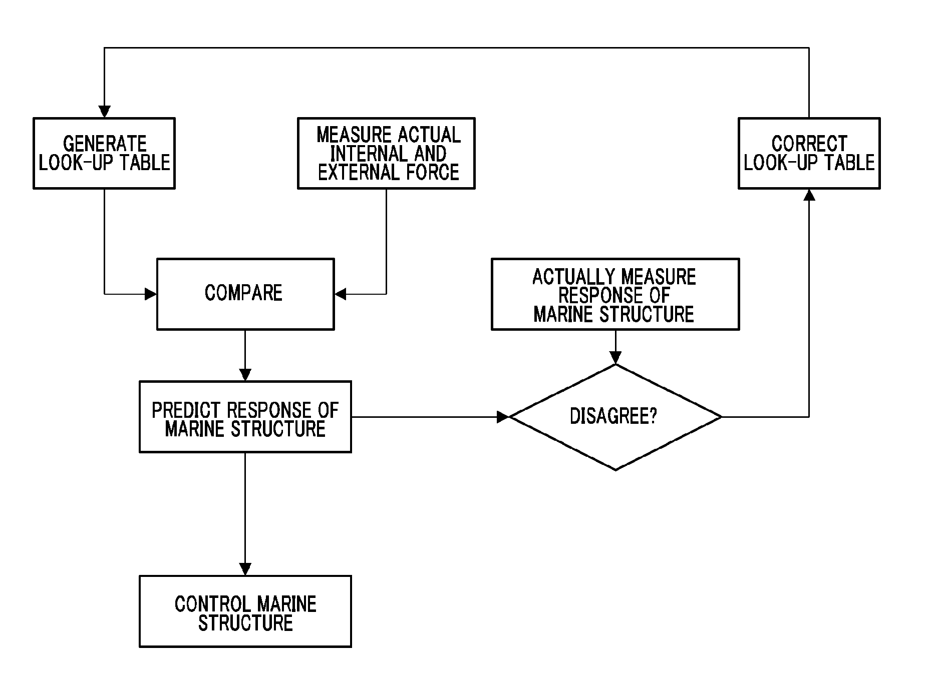
a marine structure and fuel saving technology, applied in the field of marine structure system and method, can solve the problems of short fatigue measurement durability life, buckling or deformation, and difficulty in accurately analyzing situations of monitoring methods, so as to reduce errors, extend the life span of marine structure, and rapid rescue

Active Publication Date: 2017-02-28
CYTRONIQ
View PDF18 Cites 14 Cited by
  • Summary
  • Abstract
  • Description
  • Claims
  • Application Information

AI Technical Summary

Benefits of technology

The system enables accurate, long-term monitoring of marine structures, reducing maintenance costs and preventing environmental pollution by providing real-time data on physical changes, fuel efficiency improvements, and safer operations by controlling aerodynamic and hydrodynamic forces, thus extending the lifespan of marine structures.

Problems solved by technology

Accordingly, in the pipeline installed at the sea, stresses are intensively generated at a plurality of specific or unspecified points, which results in buckling or deformation.
However, such existing monitoring methods have difficulty in accurately analyzing situations since a deformation rate caused by temperature or pressure of a marine structure is much greater than a deformation rate caused by buckling or walking.
In addition, an electric-type inclinometer currently used is installed in the sea and thus has problems such as loss by water leak caused by high hydraulic pressure and complexity in its power supply device and connection method, and thus a new measurement method allowing easier use is demanded.
In addition, sensors used in the existing monitoring methods have short fatigue measurement durability life, and thus sensors useable for a longer time are needed.
In addition, during operation of a marine structure, aerodynamic and hydrodynamic environmental internal or external force and hull stresses may cause turnover of a ship or fall of cargos, and this problem should be solved urgently.
In addition, the modern society mostly depends on motorized transportation systems which exhaust greenhouse gas, but it is widely known that exhaustion of CO2 is a main cause of global warming, climate change and ocean acidification.
However, since marine structures are overwhelming transportation means in the world trade, the amount of exhausted CO2 by marine structures occupies about 3% in the entire greenhouse gas exhaustion.
Therefore, if the fuel efficiency of marine structures is enhanced, the amount of exhausted greenhouse gas in the industry may be greatly reduced.

Method used

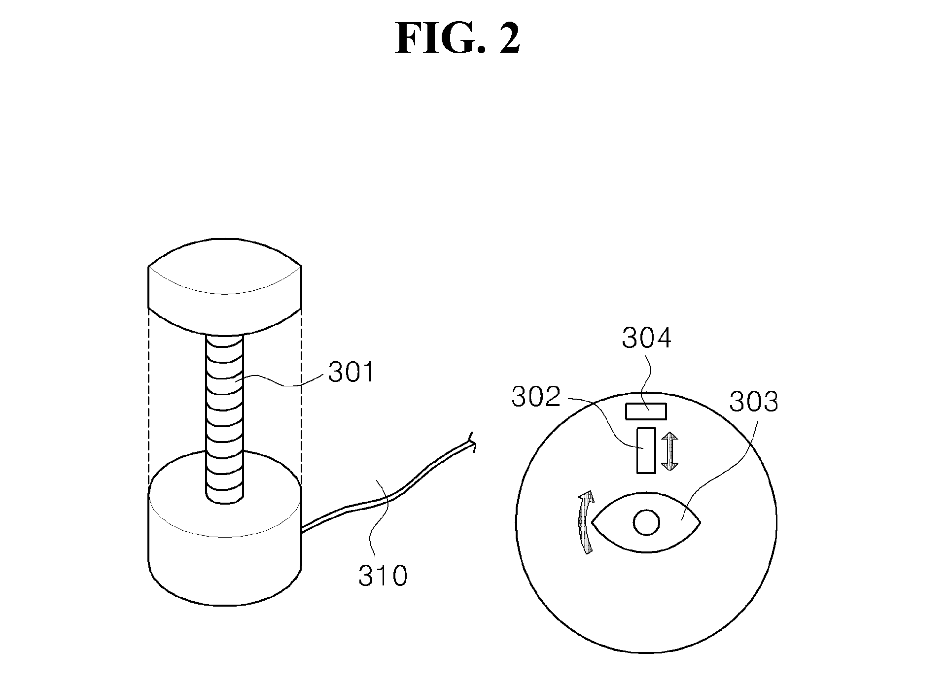

Image

  • System and method for fuel savings and safe operation of marine structure
  • System and method for fuel savings and safe operation of marine structure
  • System and method for fuel savings and safe operation of marine structure

Examples


Embodiment Construction

[0134]Objects, technical configurations and resultant effects of the present disclosure will be clearly understood from the following detailed description based on drawings accompanied in the specification of the present disclosure. Embodiments of the present disclosure will be described in detail with reference to the accompanying drawings.

[0135]Embodiments disclosed in this specification should not be interpreted or used as limiting the scope of the present disclosure. It is obvious to those skilled in the art that the descriptions including embodiments have various applications. Therefore, unless it is limited by the claims, the following embodiments are just examples for better understanding of the present disclosure and are not intended to limit the scope of the present disclosure.

[0136]The term “marine structure” used in the present disclosure has a wide meaning including all kinds of marine or submersible structures, for example, jack-up rigs, semi-sub rigs, jackets, complian...


PUM

PropertyMeasurementUnit
angleaaaaaaaaaa
time-aaaaaaaaaa
computational fluid dynamicsaaaaaaaaaa

Abstract

A system for monitoring a physical change of a marine structure includes a complex optical measuring instrument configured to detect a behavior and structural change of the marine structure by using at least one optical sensor by means of optical fiber Bragg grating.

Description

CROSS-REFERENCE TO RELATED APPLICATIONS[0001]This application is a continuation of International Application No. PCT / KR2013 / 004777 filed on May 30, 2013, which claims priority to Korean Application No. 10-2012-0057753 filed on May 30, 2012, Korean Application No. 10-2012-0057754 filed on May 30, 2012, Korean Application No. 10-2012-0057755 filed on May 30, 2012, Korean Application No. 10-2012-0129441 filed on Nov. 15, 2012, Korean Application No. 10-2012-0149412 filed on Dec. 20, 2012, Korean Application No. 10-2012-0149411 filed on Dec. 20, 2012, Korean Application No. 10-2013-0061759 filed on May 30, 2013, Korean Application No. 10-2013-0061477 filed on May 30, 2013, and Korean Application No. 10-2013-0061754 filed on May 30, 2013. The applications are incorporated herein by reference.TECHNICAL FIELD[0002]The present disclosure relates to a system and method for monitoring physical changes of a marine structure in real time with a complex optical measuring instrument by using an o...

Claims


Application Information

Patent Timeline
Patent Type & Authority Patents(United States)
IPC IPC(8): G01N25/72G01M3/00B63B9/02B63B9/00B63B9/08G01B11/16G01L1/24G01S17/93G01S13/86G01S13/93E21B17/01B63J99/00G01S13/95B63B71/20G01S13/937
CPCB63B9/002B63B9/001B63B9/02B63B9/08E21B17/01G01B11/16G01B11/18G01L1/246G01M3/00G01S13/865G01S13/9307G01S17/93B63B9/003B63J2099/008G01S13/956Y02T70/146G01L5/167G01L5/0038G01D5/35316G01S13/937B63B79/10B63B79/15Y02A20/00Y02A90/10Y02T70/10B63B79/30B63B79/40Y02T70/00B63B49/00B63B71/10B63B71/00B63B71/20B63B79/00
Inventor LEE
Owner CYTRONIQ
Learn More