
Surgical instrument

a surgical instrument and instrument body technology, applied in the field of surgical instruments, can solve the problem of having to be previously drilled into the bone,

Active Publication Date: 2017-02-28
AO TECH AG
View PDF5 Cites 474 Cited by
  • Summary
  • Abstract
  • Description
  • Claims
  • Application Information

AI Technical Summary

Benefits of technology

[0009]the ease to use due to a single instrument to drill a hole into a bone and to measure the bone quality;
[0010]to avoid the friction between the probe and a guide wire of known probes;
[0012]to have dimension compatibility with future implant design making the redesign of the probe and thresholds assessment virtually not necessary.
[0017]Furthermore, the flat surface will not affect the wire cutting properties and the cutting edge will not affect the torque measurement.

Problems solved by technology

Therefore, this known device shows the disadvantage that a hole has to be previously drilled into the bone by using a separate tool.

Method used


Image

  • Surgical instrument
  • Surgical instrument

Examples


example 1

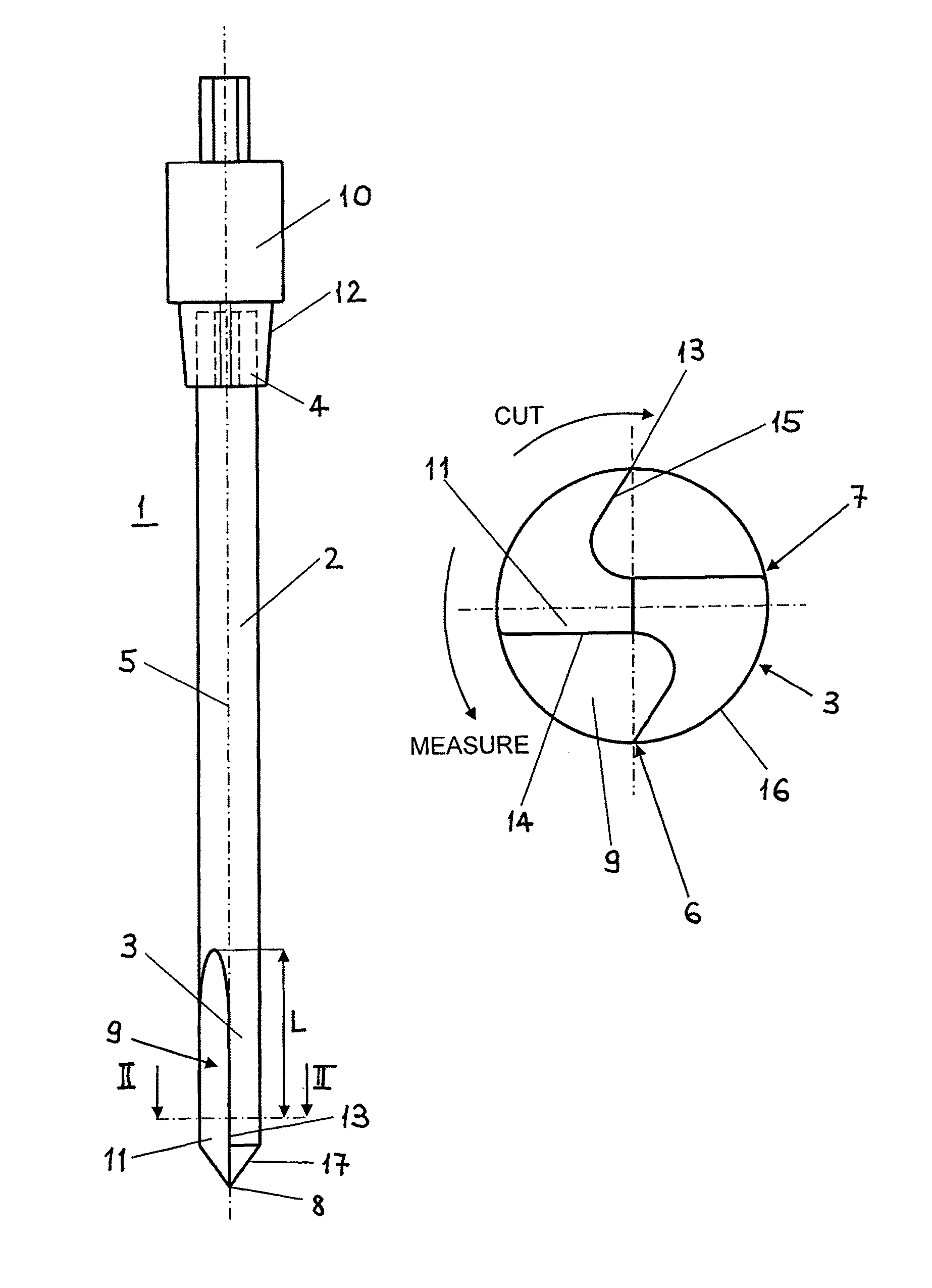
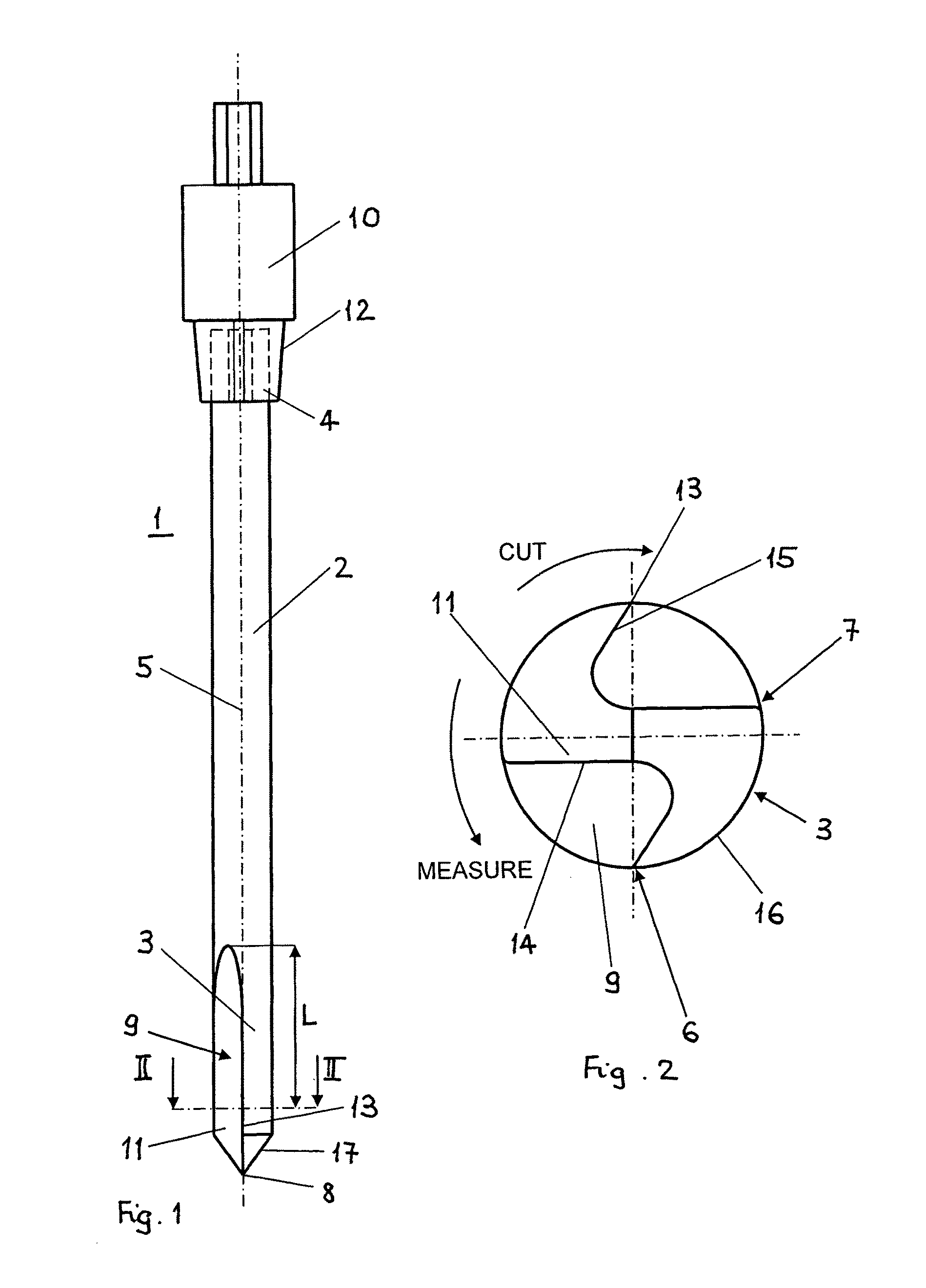
[0049]During the proximal locking procedure of an intramedullary nail implanted in the proximal femur the following steps are performed:[0050]1) fastening a suitable aiming guide to the proximal end of the intramedullary nail;[0051]2) inserting a trocar combination including a tissue protection sleeve together with a drill bushing and a trocar into the aiming guide in a desired position;[0052]3) attaching a guide wire aiming device to the aiming guide;[0053]4) adjusting the insertion depth of the intramedullary nail by using an X-ray device;[0054]5) adjusting the orientation of the intramedullary nail in a true lateral position of the X-ray device;[0055]6) performing a stab incision in the area of the trocar tip and advancing the trocar combination through the soft tissue as far as the lateral cortical bone surface;[0056]7) removing the trocar;[0057]8) opening the lateral cortex;[0058]9) inserting the shaft 2 of the surgical instrument 1 into the drill bushing;[0059]10) drilling a h...


PUM


Abstract

Surgical instrument (1) comprising a longitudinal shaft (2) with a tip portion (3), a rear portion (4) and a longitudinal axis (5) and rotatable in the clock-wise and in the counter-clockwise direction around the longitudinal axis (5), said surgical instrument (1) further comprising: A) first means (6) for drilling a hole in a bone by rotation of the shaft (2) in one of the two directions; B) second means (7) for crushing bone tissue when the shaft (2) rotates in the other of the two directions; and C) a torque sensor (10) coupled to the shaft (2). Method for measuring the local mechanical resistance of a porous body comprising the steps of: a) drilling a hole to a desired depth into a porous body by advancing and rotating the shaft (2) in a first sense of rotation, preferably clockwise so that said first means (6) are active; b) hammering the shaft (2) gently further into the porous body as far as the tip portion (3) of the shaft (2) has reached a desired measuring position; and c) performing the torque measurement by rotating the shaft (2) in the opposite second sense of rotation, preferably counter-clockwise so that said second means (7) are active.

Description

BACKGROUND OF THE INVENTION[0001]1. Field of the Invention[0002]The invention relates to a surgical instrument, to a method for measuring the local mechanical resistance of a porous body and to the use of the surgical instrument for estimating the quality of cancellous bone.[0003]Known probes for measuring the mechanical resistance of porous bone commonly comprise a cannulated probe that is slid on a K-wire previously inserted in the bone. However, during insertion the K-wire is mostly slightly deformed resulting in a variable contact area between the K-wire and the inner surface of the cannulation of the probe. The larger being the contact area between the K-wire and the probe the more being the K-wire deformed (resulting in a force component normal to the inner probe surface) the higher is the friction between the K-wire and the probe. The higher the friction between probe and the K-wire is the higher will be (artificially) the recorded torque. The lower the bone mineral density i...

Claims


Application Information

Patent Timeline
Patent Type & Authority Patents(United States)
IPC IPC(8): A61B17/00A61B17/88A61B17/16A61B5/00
CPCA61B90/06A61B5/4509A61B17/1615A61B17/1664A61B17/88A61B17/1668A61B2090/064A61B2090/066
Inventor BRIANZA, STEFANOSCHWYN, RONALD
Owner AO TECH AG
Learn More