
Radio frequency communication with antenna index coding

Active Publication Date: 2017-02-21
WISCONSIN ALUMNI RES FOUND
View PDF4 Cites 0 Cited by
  • Summary
  • Abstract
  • Description
  • Claims
  • Application Information

AI Technical Summary

Benefits of technology

The invention provides a mechanism for improving the efficiency of wireless communication by transmitting extra bits of information without increasing energy consumption. This is achieved by using antenna hopping, where a transmitter switches between multiple passive antennas and the receiver deciphers the transmit antenna's index to determine which antenna to use for transmitting data. The invention can be applied to different wireless protocols like Wi-Fi and ZigBee. It allows for a fine-grained antenna hopping, reduces decoding errors, and optimizes the tradeoff between bandwidth and energy efficiency. Additionally, the invention avoids underutilization of antenna index coding by switching antenna per sample in order to convey more information per unit time.

Problems solved by technology

Such components in an RF chain account for a significant amount of an RF transceiver's power cost, and MIMO power consumption typically increases linearly with the number of RF chains.
As a result, the addition of RF chains and antennas often nullifies the improvement in link capacity, which may result in even lower energy-per-bit than SISO.

Method used


Image

  • Radio frequency communication with antenna index coding
  • Radio frequency communication with antenna index coding
  • Radio frequency communication with antenna index coding

Examples


Embodiment Construction

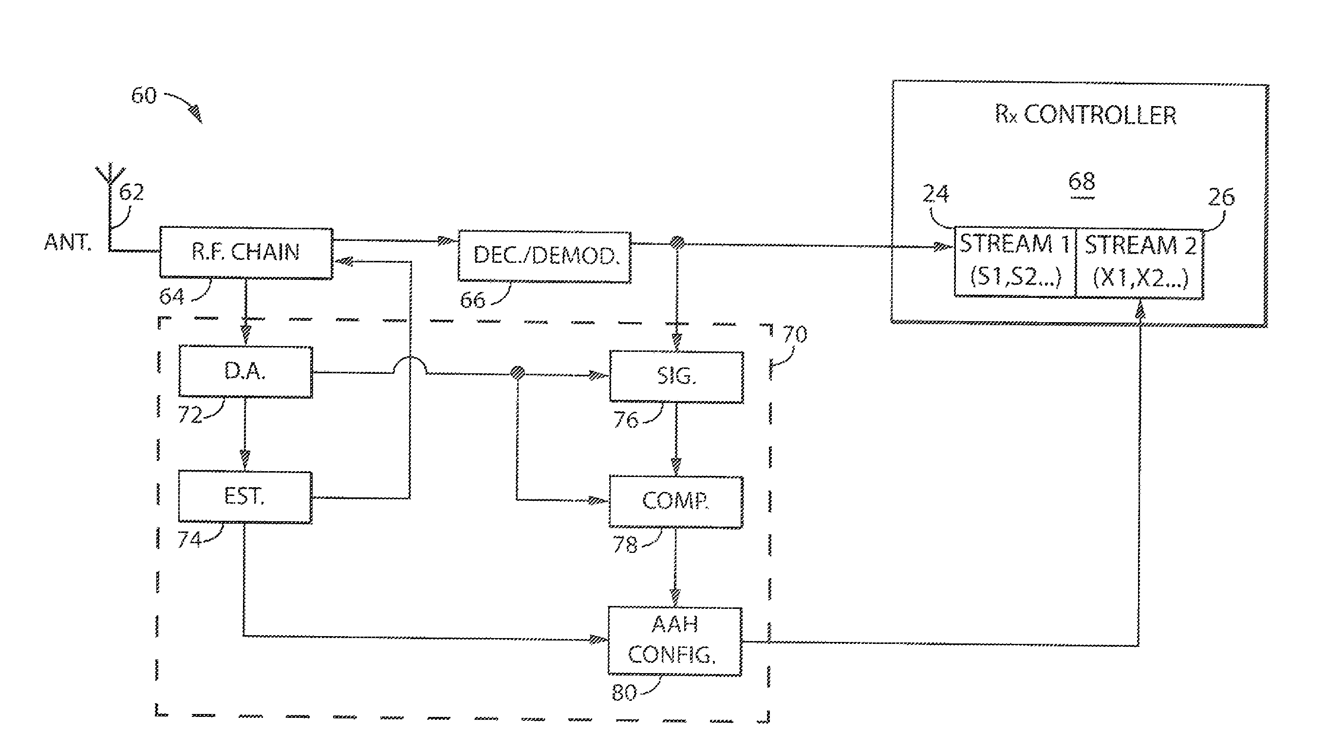
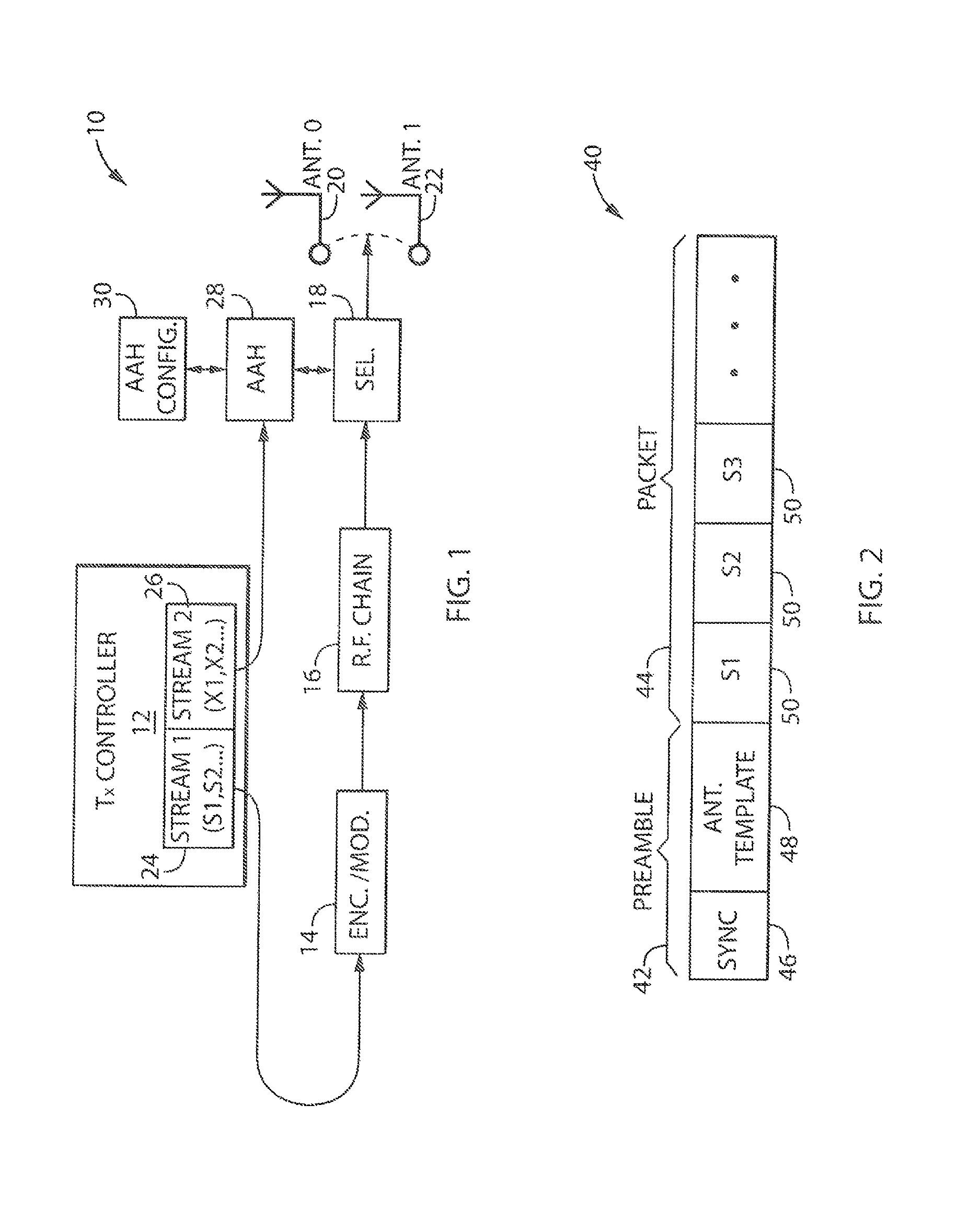
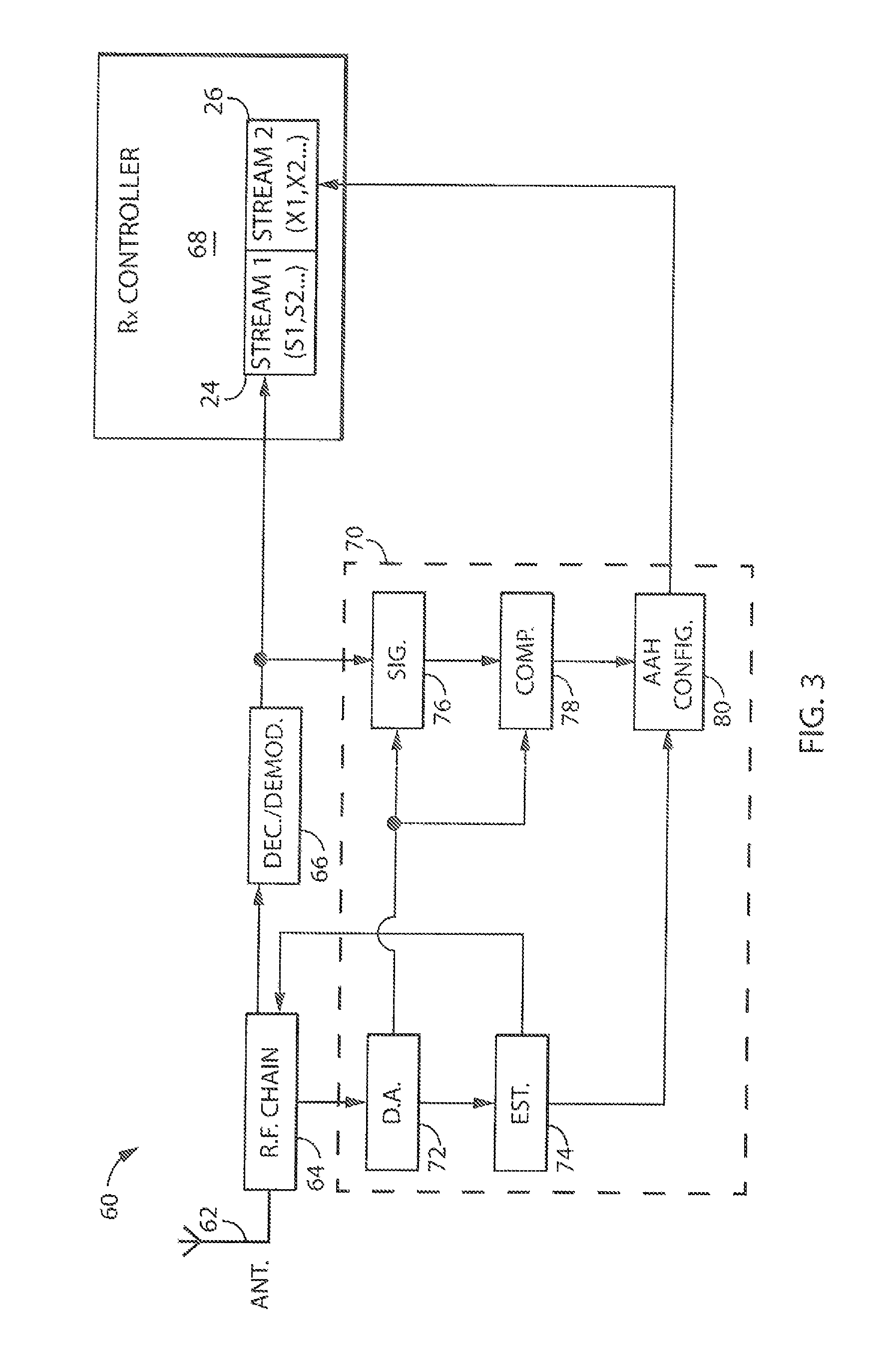
[0036]Referring now to FIG. 1, a diagram of an RF communication system 10 (transmit system) which may be used for wireless data transmission is provided in accordance with an embodiment of the invention. Although exemplified in FIG. 1 as a transmitter, the RF communication system 10 will typically be part of a transceiver in a larger wireless communicating device, such as a smartphone, tablet, battery powered or other device, allowing both transmit and receive functions. For example, the RF communication system 10 may be part of a ZigBee communication network, such as with respect to the IEEE 802.15.4 specification.

[0037]The RF communication system 10 may include a controller 12 in communication with an encoder / modulator 14. The encoder / modulator 14, in turn, may be in communication with an RF chain 16 (or RF transmitter or transceiver), which may typically include a Digital to Analog Converter (DAC), amplifiers, filters, signal conditioners and / or other elements for effecting RF co...


PUM


Abstract

The inventors have recognized that in RF communication systems, by switching between transmit antennas of an RF transmitter on a sub-symbol basis (antenna index coding), and / or by adaptively determining how often antenna switching occurs (adaptive antenna hopping), an increased amount of data may be wirelessly transmitted to an RF receiver without significantly increasing energy consumption. The inventors have determined that in certain systems, such as ZigBee, data symbols consist of elementary waveform patterns, and that such waveform patterns for transmit antennas may be stored by an RF receiver for later determining transmit antennas for data symbols. The inventors have also determined that the invention may be applied in the frequency domain, such as to OFDM, by storing subcarrier waveform patterns for particular transmit antennas and later determining transmit antennas for subcarriers of data symbols.

Description

STATEMENT REGARDING FEDERALLY SPONSORED RESEARCH OR DEVELOPMENT[0001]This invention was made with government support under CNS-1318292, CNS-1343363, CNS-1350039, and CNS-1404613 awarded by the National Science Foundation. The government has certain rights in the invention.FIELD OF THE INVENTION[0002]The present invention is directed to the field of Radio Frequency (RF) communication systems, and more particularly, to systems and methods for improving data transmission in such systems.BACKGROUND OF THE INVENTION[0003]In Radio Frequency (RF) communication systems, Multiple-Input, Multiple-Output (MIMO) has been an important enabling technology for high-rate wireless standards in communications. Compared with conventional Single-Input, Single-Output (SISO) links, a MIMO transmitter can code the same data symbols through multiple antennas, thus achieving a diversity gain. A MIMO transmitter can also allow parallel transmission of different data symbols through different antennas, thus a...

Claims


Application Information

Patent Timeline
IPC IPC(8): H04L1/02H04L1/00H04B7/06H04B7/08H04B7/04H04L5/00
CPCH04B7/0604H04L1/0033H04B7/0825H04L5/0023H04B7/0413
Inventor ZHANG, XINYUSUR, SANJIBWEI, TENG
Owner WISCONSIN ALUMNI RES FOUND
Learn More