
Catalysts and methods of using the same

a catalyst and catalyst technology, applied in the field of catalysts, can solve the problem that catalysts are unselectively exposed to materials in a chemical reaction, and achieve the effect of reducing the c:o ratio, facilitating the hydrotreatment process, and facilitating the hydrodeoxygenation reaction

Active Publication Date: 2017-02-14
IOWA STATE UNIV RES FOUND
View PDF24 Cites 3 Cited by
  • Summary
  • Abstract
  • Description
  • Claims
  • Application Information

AI Technical Summary

Benefits of technology

[0009]Various embodiments of the present invention provide advantages over other mesoporous silica nanoparticles and methods of using the same, including some advantages that are unexpected. In some embodiments, as compared to other catalysts, the catalyst can provide greater catalytic activity in chemical transformations of molecules such as fatty acids, fatty acid esters, monoglycerides, diglycerides, and triglycerides. In some embodiments, the catalyst can give a greater selectivity for catalyzing particular hydrotreatment reactions over other hydrotreatment reactions, such as of fatty acids, as compared to other hydrotreatment catalysts. Various embodiments of the catalyst allow better control over the product distribution of hydrotreatment, such as of fatty acids, than other catalysts, providing a hydrocarbon product (e.g., green diesel) that is more easily and more efficiently used than other hydrotreatment products. In various embodiments, the catalyst can be provided with a lower cost than other hydrotreatment catalysts. In various embodiments, the catalyst can provide various advantages at lower cost than available from other catalysts or methods, such as lower cost of controlling hydrotreatment product distribution, and lower cost for a achieving a given hydrotreatment reaction rate. In some embodiments, the catalyst can provide an economical, efficient and sulfur-free method for converting microalgal oil into green diesel.
[0010]Various embodiments of the catalyst allow better control over the product distribution of hydrotreatment, such as of fatty acids, than other catalysts, providing a hydrocarbon product (e.g., green diesel) that is more easily and more efficiently used than biodiesel. For example, green diesel can have less oxygen atoms than biodiesel, or no oxygen atoms, giving the green diesel higher energy density that biodiesel. For example, green diesel can have less unsaturated hydrocarbons than biodiesel, or no unsaturated hydrocarbons, which can result in greater storage stability and less likelihood of oxidation and degradation over time than biodiesel. For example, the heat of combustion of green diesel can be higher than the heat of combustion than biodiesel.
[0011]In various embodiments of an adsorbent catalyst, the combination of the ability to not only separate particular substances from a mixture but also to catalyze the chemical transformation of those substances is unique and advantageous. In some embodiments, the proximity of the adsorbent functional groups and the catalytic material in the adsorbent catalyst yields desirable or advantageous and unexpected properties.
[0013]In some embodiments, the selectivity of a particular adsorbent catalyst toward various chemical reactions of a molecule adsorbable by the adsorbent groups can be different when the molecule is adsorbed to an adsorbent group on the nanoparticle, versus when the molecule is not adsorbed to an adsorbent group on the nanoparticle. Thus, in various embodiments, the selectivity of the chemical reactions of a first molecule catalyzed by the catalytic material can be advantageously modulated by allowing the adsorbent groups to adsorb the first molecule prior to subjecting the first molecule and the adsorbent catalyst to conditions so that the catalytic material catalyzes a chemical transformation of the first molecule.
[0014]In some examples, by allowing an adsorbent catalyst including a hydrotreatment catalyst to first adsorb a fatty acid from a mixture, and then subjecting the adsorbent catalyst with the adsorbed fatty acid to conditions effective for the catalytic material to catalyze hydrotreatment, the products formed can advantageously and unexpectedly have a higher C:O ratio than can be achieved when the fatty acid is hydrotreated using the catalytic material but with the catalytic material not having selectively adsorbent groups proximate thereto. In some examples, by allowing an adsorbent catalyst including a hydrotreatment catalyst to first adsorb a fatty acid from a mixture, and then subjecting the adsorbent catalyst with the adsorbed fatty acid to conditions so that the catalytic material catalyzes hydrotreatment, the selectivity of the hydrotreatment toward hydrodeoxygenation can be higher as compared to the cracking and decarboxylation than can be achieved when the fatty acid is hydrotreated using the catalytic material but not having selectively adsorbent groups proximate thereto, thereby yielding an increased average hydrocarbon length of the resulting product mixture; thus, various embodiments produce hydrocarbon mixtures having higher C:O ratios, higher cetane numbers, with less need for further processing, and / or are formed with less environmentally damaging release of CO2.
[0015]In the manufacture of green diesel, fatty acids in the feedstock can form compounds by combining with certain catalytic materials, such as basic transesterification catalysts, to form soaps and consuming catalyst, thus reducing the efficiency of the process. In certain embodiments, the adsorbent catalyst can be used to efficiently remove fatty acids from a green diesel feedstock, and subsequently to conveniently chemically hydrotreat the removed fatty acids, forming hydrocarbon mixtures that can be useful as fuel having better qualities than hydrotreated fatty acids produced by other methods, such as higher C:O ratio, and lower cost. The method of production can have less complexity and less energy use, and allow for the use of cheaper starting materials, such as for bio-diesel production. In certain embodiments, the adsorbent catalyst can be reused multiple times for separation of one or more materials from a mixture and subsequent catalytic conversion of the materials.

Problems solved by technology

Many catalysts lack selectivity Generally, catalysts are unselectively exposed to materials in a chemical reaction.

Method used


Image

  • Catalysts and methods of using the same
  • Catalysts and methods of using the same
  • Catalysts and methods of using the same

Examples


example 1

Mesoporous Silica Nanoparticles Including Iron Nanoparticles

[0107]Materials.

[0108]Pluronic P104 was generously provided by BASF. Tetramethyl ortho silicate (TMOS), oleic acid, and Sylon (BSTFA (N,O-bis(trimethylsilyl)trifluoroacetamide) and TMCS (trimethylchlorosilane), 99:1) were purchased from Sigma Aldrich. Iron (III) Nitrate [Fe(NO3)3.9H2O] was purchased from Fisher Scientific. All reagents were used as received without further purification.

[0109]Characterization.

[0110]Surface analysis of the catalyst was performed by nitrogen sorption isotherms in a Micromeritics Tristar analyzer. The surface areas were calculated by the Brunauer-Emmett-Teller (BET) method and the pore size distribution was calculated by the Barrett-Joyner-Halenda (BJH) method. The small angle powder X-ray diffraction (XRD) patterns were obtained with a Rigaku Ultima IV diffractometer using Cu target at 40 kV and 44 mA. Cu Kβ was removed using a monochromator. For transmission electron microscopy measurements, ...

example 1.1

Catalyst Preparation

[0113]MSN was prepared using a nonionic block co-polymer Pluronic P104 surfactant. In a typical synthesis, P104 (7.0 g) was dissolved in aqueous HCl (273.0 g, 1.6 M). After stirring for 1 h at 56° C., tetramethylorthosilicate (TMOS, 10.64 g) was added and stirred for additional 24 h. The resulting mixture was further hydrothermally treated for 24 h at 150° C. in a high-pressure reactor. Upon cooling to room temperature, the white solid was collected by filtration, washed with copious amounts of methanol and dried in air. To remove the surfactant P104, the MSN material was heated at a ramp rate of 1.5° C. min−1 and maintained at 550° C. for 6 h. MSN was then mixed with water and stirred at room temperature in order to rehydrate and regenerate the silanol groups, followed by filtration and drying. For impregnation, Fe(NO3)3.9H2O (0.40 mmol, 0.16 g) was completely dissolved in water (0.48 mL). To this solution, the rehydrated MSN (0.4 g) was added and mixed. The sol...

example 1.2

Properties of Fe-MSN

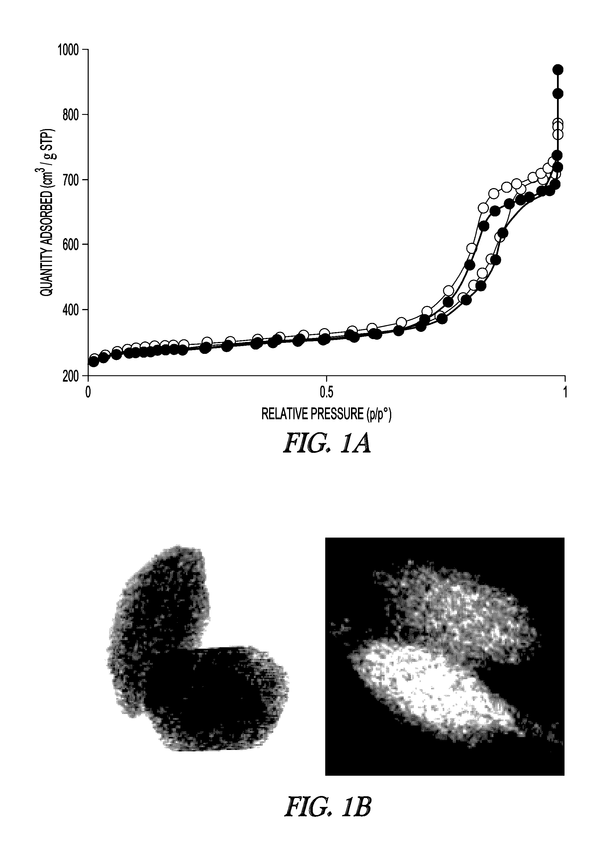
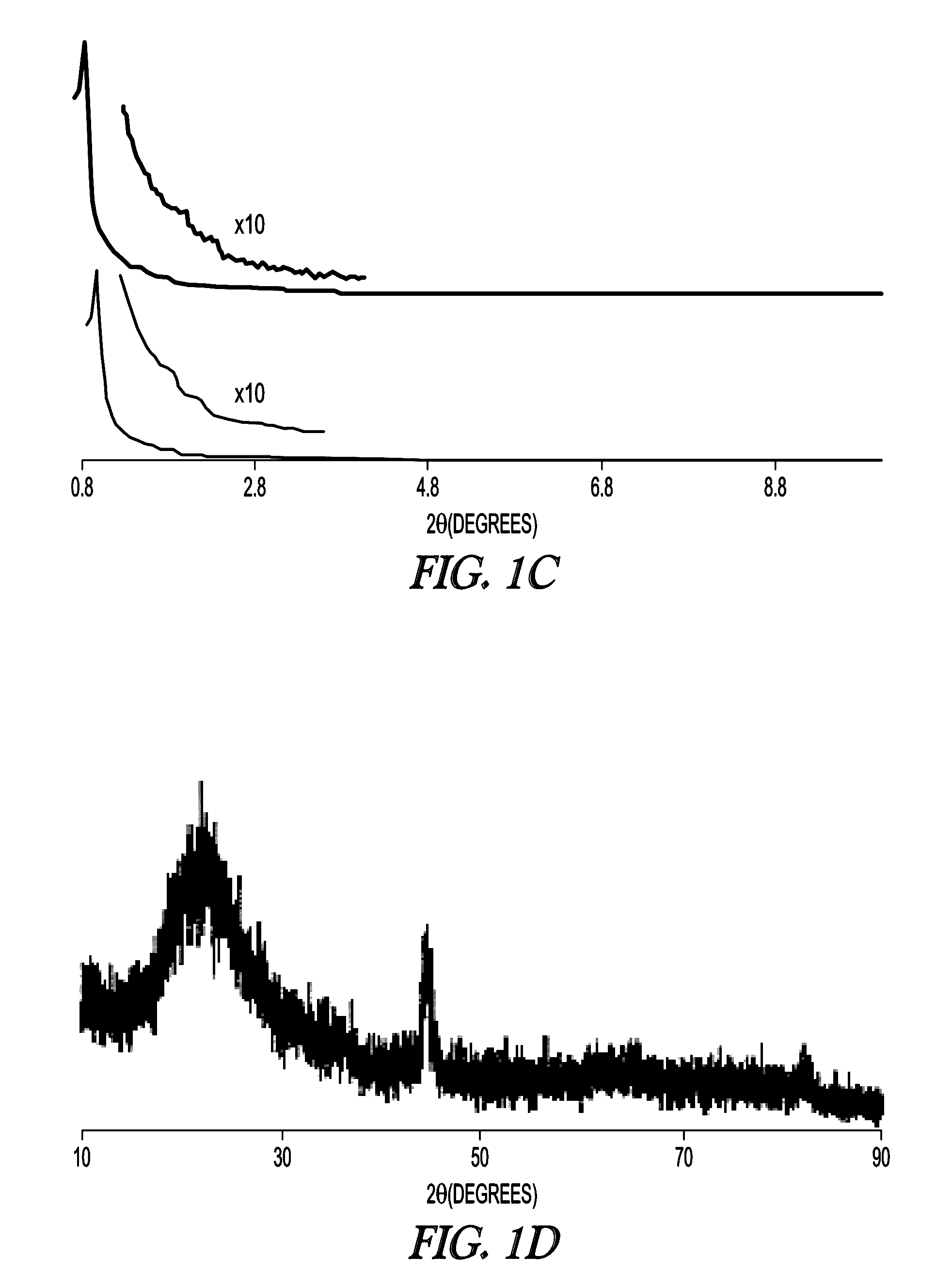
[0114]The textural properties of MSN support and Fe-MSN catalyst are summarized in Table 1. Inductively coupled plasma (ICP) measurement indicated 6.0 wt % Fe was immobilized on the MSN support. Formation of the Fe nanoparticles led to approximately 10% decrease in the surface area and pore volume of the support; however, its nitrogen sorption isotherm remained type IV, confirming retention of the mesoporous character (FIG. 1a, showing MSN (open circles) and Fe-MSN (filled circles)). TEM and scanning transmission electron microscopy (STEM) imaging suggested that the Fe nanoparticles were located mainly inside the pores of the MSN (FIG. 1b). Low angle XRD analysis confirmed that the structure of the support was not affected by the formation of Fe nanoparticles, as it preserved the p6 mm pattern typical of SBA-15 type materials (FIG. 1c, showing MSN (bottom) and Fe-MSN (top), with insets showing 10× magnified 110 and 200 reflections). Wide-angle XRD showed a patter...


PUM

PropertyMeasurementUnit
particle sizeaaaaaaaaaa
pore sizeaaaaaaaaaa
temperatureaaaaaaaaaa

Abstract

The present invention provides a catalyst including a mesoporous silica nanoparticle and a catalytic material comprising iron. In various embodiments, the present invention provides methods of using and making the catalyst. In some examples, the catalyst can be used to hydrotreat fatty acids or to selectively remove fatty acids from feedstocks.

Description

CROSS-REFERENCE TO RELATED APPLICATIONS[0001]This application is a continuation-in-part of and claims the benefit of priority under 35 U.S.C. §120 to U.S. Utility application Ser. No. 13 / 691,181 entitled “ADSORBENT CATALYTIC NANOPARTICLES AND METHODS OF USING THE SAME,” filed Nov. 30, 2012, the disclosure of which is incorporated herein in its entirety by reference.STATEMENT OF GOVERNMENT SUPPORT[0002]This invention was made with Government support under contract no. DE-AC02-07CH11358 awarded by the U.S. Department of Energy. The U.S. Government has certain rights in this invention.BACKGROUND OF THE INVENTION[0003]Petroleum-derived solvents and fuels are of environmental concern and are under legislation to be replaced by biorenewable substitutes that afford reduced environmental impact. Unpredictable petroleum prices and the increasing desire for energy independence and security have led to burgeoning research activities directed toward developing a variety of alternative fuels. Am...

Claims


Application Information

Patent Timeline
Patent Type & Authority Patents(United States)
IPC IPC(8): C07C1/22C07C1/207B01J23/745B01J37/10B01J37/02B01J37/00B01J21/08B01J23/755B01J23/881B01J23/89B01J29/03B01J35/00B01J35/10B01J37/18
CPCB01J35/002B01J35/006B01J35/0013B01J35/1019B01J35/1042B01J35/1061B01J37/0018B01J37/0201B01J37/0207B01J37/10C07C1/2078C07C9/22C07C1/22B01J21/08B01J23/745B01J23/755B01J23/881B01J23/8906B01J29/0308B01J37/18C07C2521/08C07C2523/745C07C2523/755Y02P20/52Y02P20/588Y02P20/50
Inventor SLOWING, IGOR IVANKANDEL, KAPIL
Owner IOWA STATE UNIV RES FOUND
Learn More