
Pluggable electrical receptacle and universal wall box and methods of use thereof

a technology of electrical receptacles and universal wall boxes, which is applied in the direction of switching with two operating positions, connecting devices, and fixed contacts to operating parts, etc., can solve the problems of higher costs than would otherwise be incurred through a simpler apparatus and installation method, and achieve the effect of reducing labor costs, reducing the number of stock keeping units, and quick installation

Active Publication Date: 2017-02-07
MOSS J
View PDF37 Cites 7 Cited by
  • Summary
  • Abstract
  • Description
  • Claims
  • Application Information

AI Technical Summary

Benefits of technology

The patent is about a pluggable electrical receptacle and universal wall box that can be easily installed and changed without interrupting the power supply to downstream wall boxes. The technical effect of this invention is that it provides a convenient and efficient solution for updating and upgrading electrical infrastructure without causing any disruptions to the power supply. Additionally, its quick installation speed makes it simple to install in a hurry.

Problems solved by technology

Further, it is often necessary to replace a single, defective electrical receptacle.
All of these steps are labor intensive, such as require considerable skill and manual dexterity to bend and manipulate the heavy gauge power wires and mentally challenging to understand the complex wiring schemes and generally require the services of a licensed electrician, resulting in higher costs than would otherwise be incurred through a simpler apparatus and method of installation.

Method used


Image

  • Pluggable electrical receptacle and universal wall box and methods of use thereof
  • Pluggable electrical receptacle and universal wall box and methods of use thereof
  • Pluggable electrical receptacle and universal wall box and methods of use thereof

Examples


Embodiment Construction

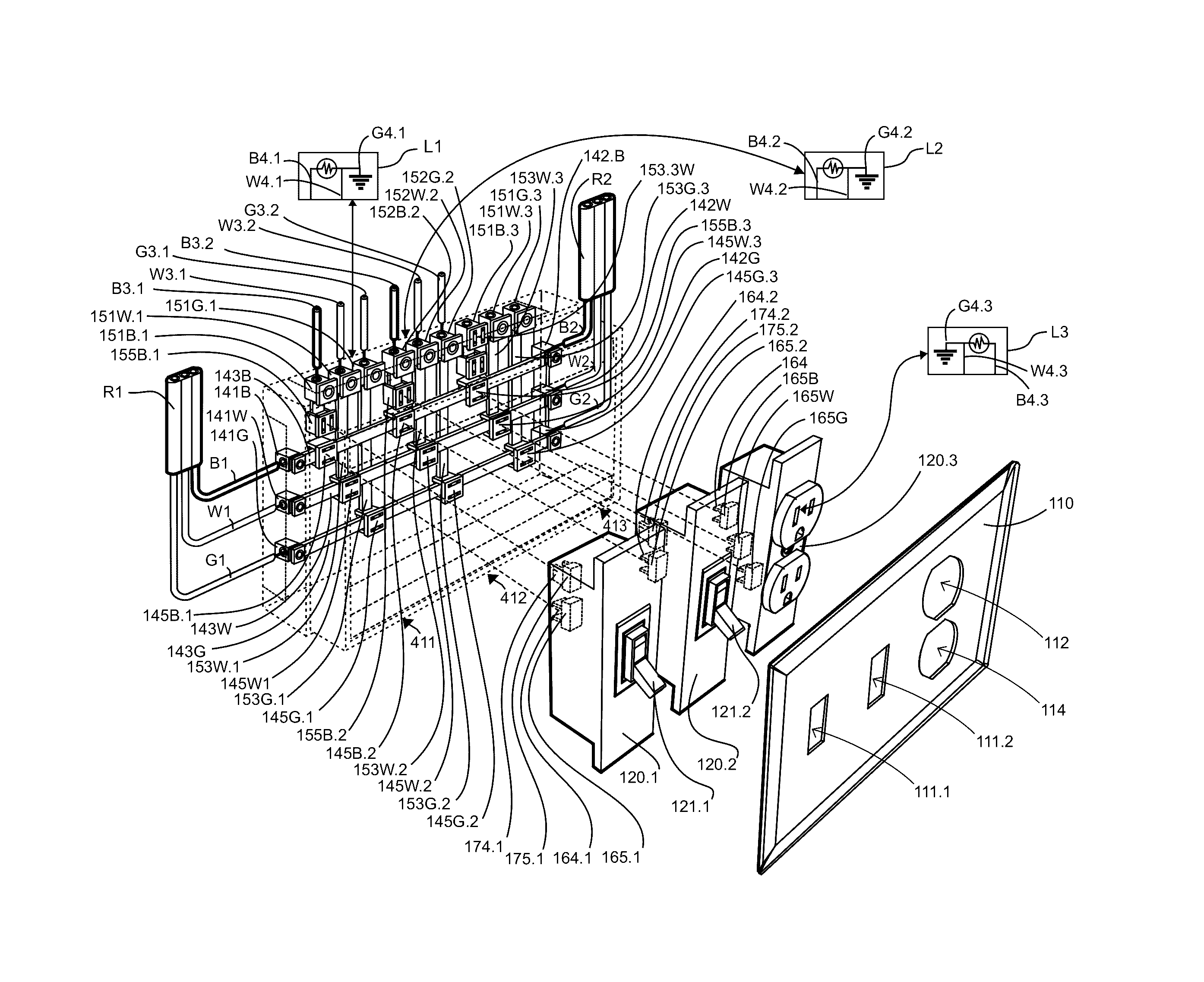
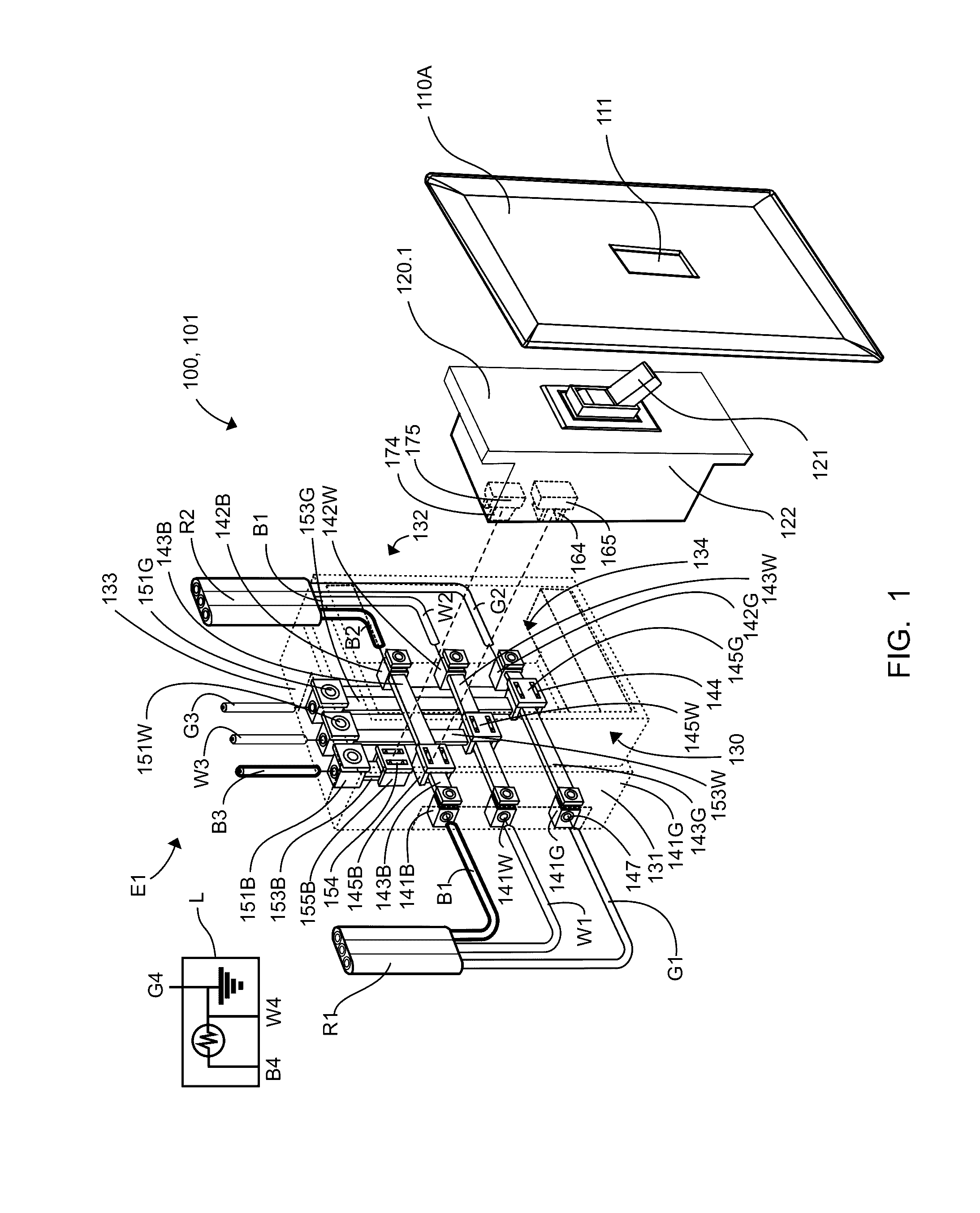
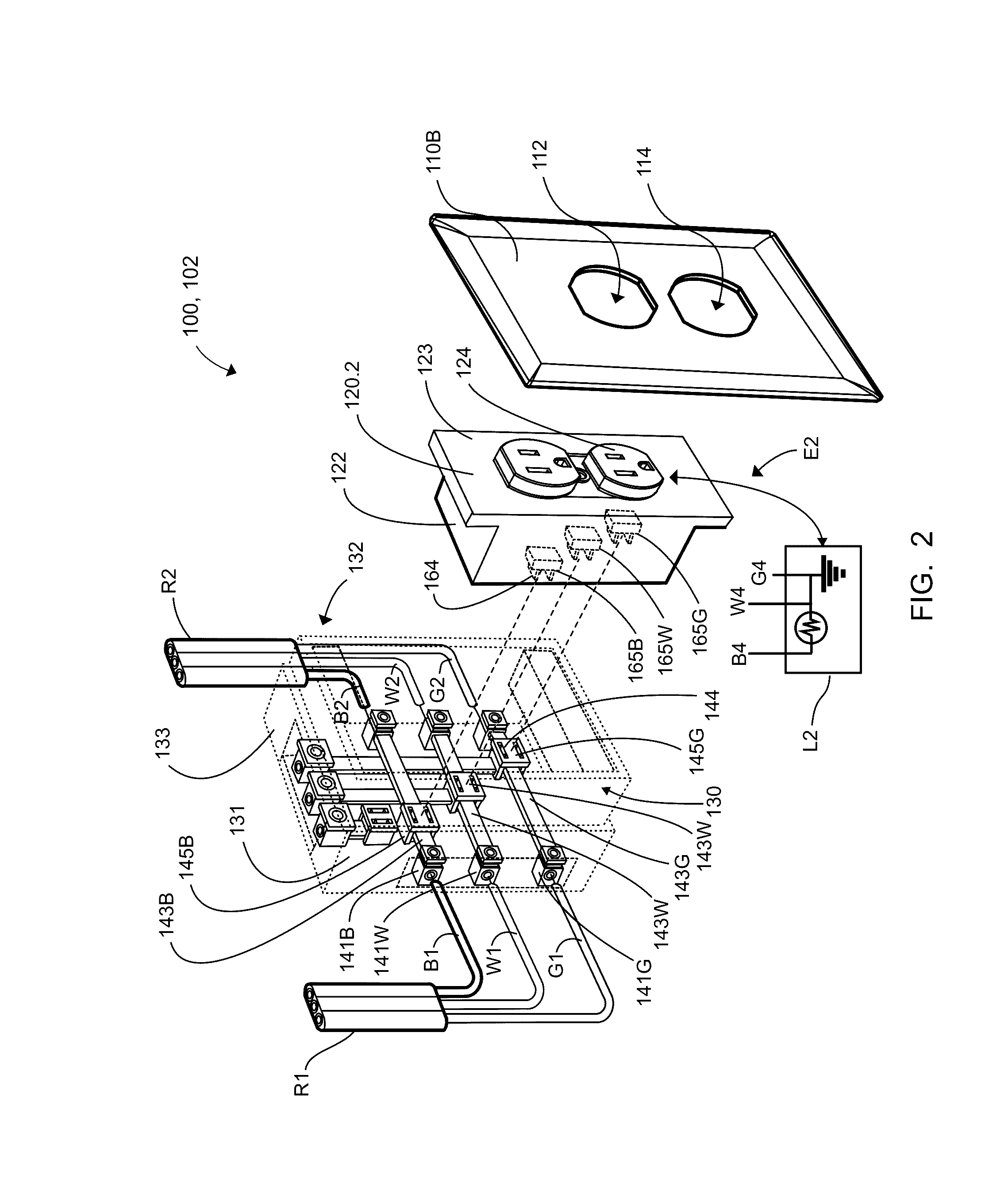
[0043]In describing the exemplary embodiments of the present disclosure, as illustrated in FIGS. 1-6, specific terminology is employed for the sake of clarity. The present disclosure, however, is not intended to be limited to the specific terminology so selected, and it is to be understood that each specific element includes all technical equivalents that operate in a similar manner to accomplish similar functions. Embodiments of the claimed invention may, however, be embodied in many different forms and should not be construed to be limited to the embodiments set forth herein. The examples set forth herein are non-limiting examples, and are merely examples among other possible examples.

[0044]Electrical language used herein may be used interchangeably, such as black-power-hot, white-neutral, and green-ground.

[0045]Referring now to FIGS. 1, 2, and 6 by way of example, and not limitation, therein is illustrated an example embodiment electrical receptacle assembly 100, wherein electric...


PUM


Abstract

An electrical wall box having a plurality of wire in and wire out power terminals on an exterior of the electrical wall box, wherein each set of wire in and wire out power terminals are electrically connected to one of a plurality of internal insulated distribution busses within the electrical wall box, each of the distribution buses has one or more first quick connect terminals electrically connected thereto one of the distribution buses; wherein electrical wall box further includes a plurality of switch wiring terminals on an exterior of the electrical wall box, each of the plurality of switch wiring terminals includes an insulated electrical tap connecting one of the switch wiring terminals to one of the plurality of internal insulated distribution busses or to a quick connect terminal within the electrical wall box; one or more pluggable electrical receptacles, each of the one or more pluggable electrical receptacles includes two or more second quick connect terminals to electrically connect thereto one of said one or more first quick connect terminals; and a cover plate.

Description

FEDERALLY SPONSORED RESEARCH OR DEVELOPMENT[0001]NonePARTIES TO A JOINT RESEARCH AGREEMENT[0002]NoneREFERENCE TO A SEQUENCE LISTING[0003]NoneBACKGROUND[0004]Technical Field of the Invention[0005]The present invention relates generally to electrical receptacles or fixtures, and more specifically to pluggable quick connect electrical receptacles or fixtures and wall box.[0006]Description of Related Art[0007]During construction of buildings, both commercial and residential, it is common to provide an electrical wall box for receiving an electrical receptacle, such as, an outlet or a switch. The electrical wall box is typically secured to the side of a vertical stud. Once the wall box is installed, wallboard is typically installed over the studs and an opening is cut in the wallboard in order to pass the electrical receptacle through the wallboard into the wall box. Electrical wiring from a power source or load enters the wall box via an opening therein, wherein the electrical wiring is...

Claims


Application Information

Patent Timeline
IPC IPC(8): H01R13/60H01H23/24H01R25/00H01H23/04H01R13/639H01R24/52
CPCH01R25/006H01H23/24H01H23/04H01H2205/002H01R13/6395H01R24/525H01R25/161H02G3/08
Inventor MOSS, J
Owner MOSS J
Learn More