
Laser beam mixing apparatus and method of sealing organic light emitting diode display using the same

a technology of organic light emitting diodes and mixing apparatuses, which is applied in the direction of chemistry apparatus and processes, instruments, optical elements, etc., can solve the problem of not having uniform energy of laser beams over the entire cross-section, and achieve uniform energy density and improve sealing quality.

Active Publication Date: 2017-02-07
SAMSUNG DISPLAY CO LTD
View PDF8 Cites 0 Cited by
  • Summary
  • Abstract
  • Description
  • Claims
  • Application Information

AI Technical Summary

Benefits of technology

The apparatus achieves uniform energy distribution across the sealing region of OLED displays, enhancing sealing quality by preventing bubbles and cracks in the sealant, resulting in a more reliable and efficient bonding process.

Problems solved by technology

A laser beam does not have uniform energy over the entire cross-section thereof, although the laser beam is barely diffused while traveling.

Method used


Image

  • Laser beam mixing apparatus and method of sealing organic light emitting diode display using the same
  • Laser beam mixing apparatus and method of sealing organic light emitting diode display using the same
  • Laser beam mixing apparatus and method of sealing organic light emitting diode display using the same

Examples


Embodiment Construction

[0047]Reference will now be made in detail to the exemplary embodiments of the present invention, examples of which are illustrated in the accompanying drawings, wherein like reference numerals refer to the like elements throughout. The exemplary embodiments are described below, in order to explain the aspects of the present invention, by referring to the figures.

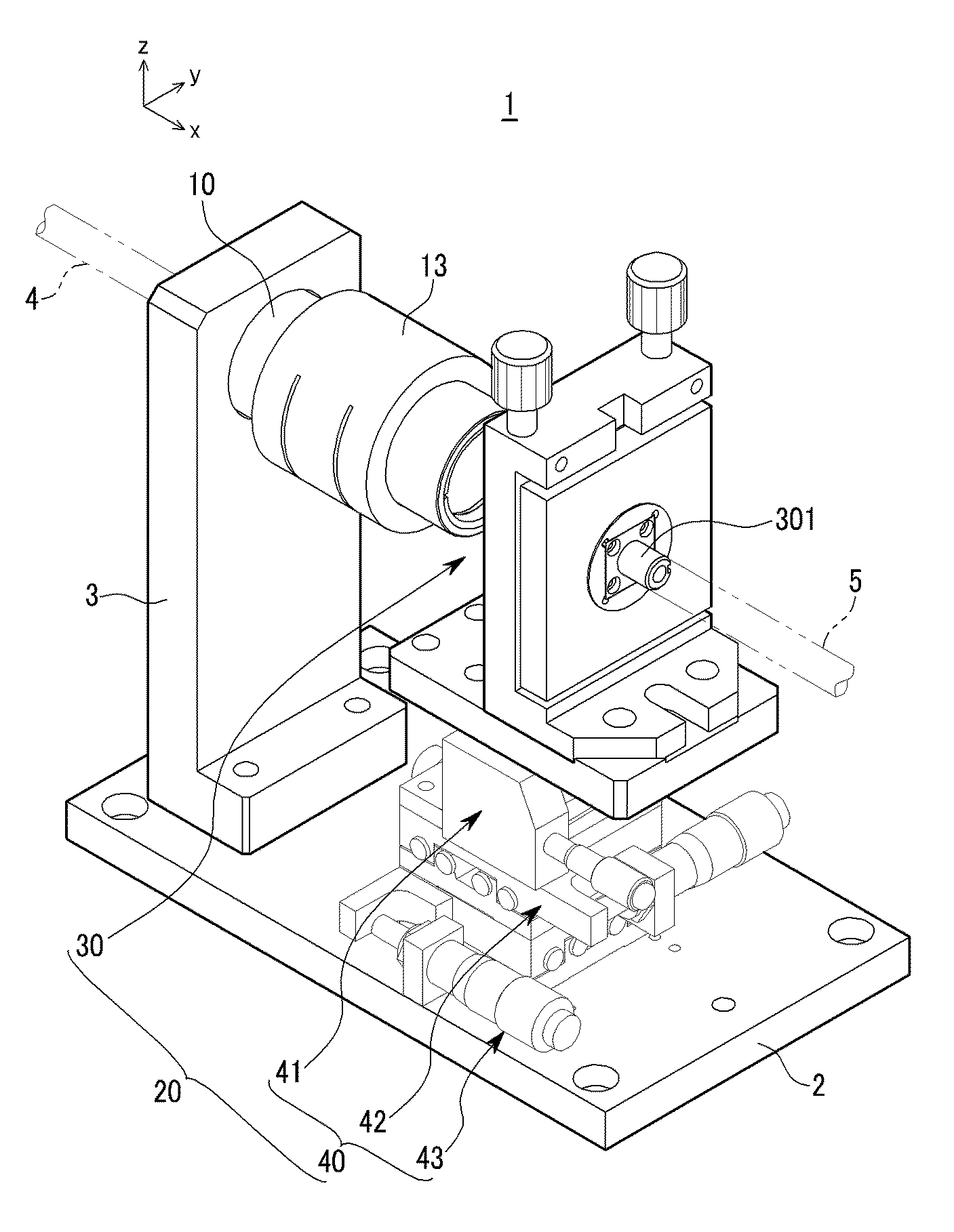
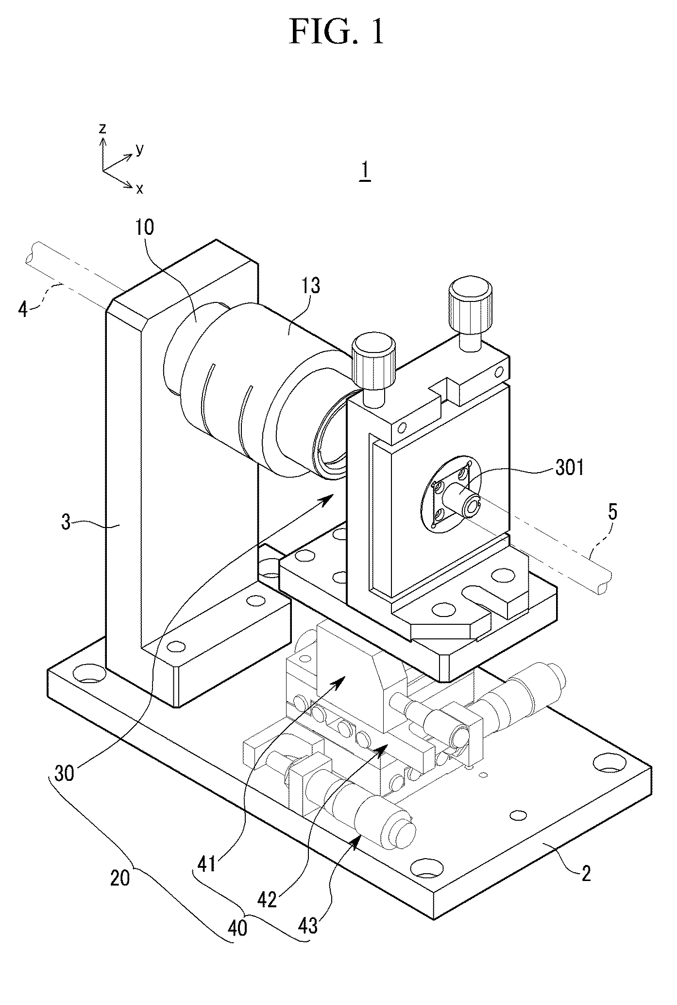
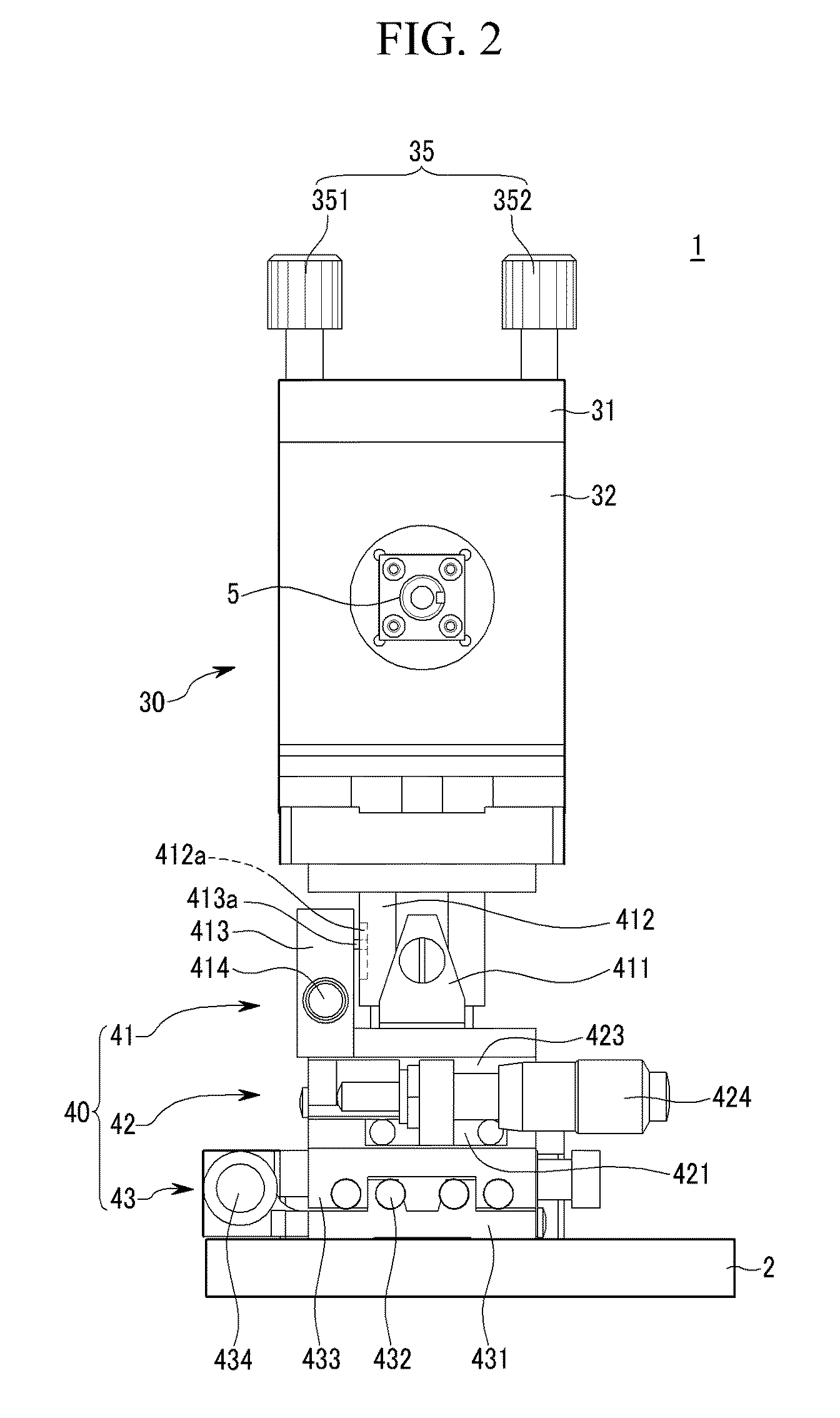
[0048]FIG. 1 is a perspective view of a laser beam mixing apparatus 1, according to an exemplary embodiment of the present invention, and FIG. 2 is a front view of the laser beam mixing apparatus 1. Referring to FIGS. 1 and 2, the laser beam mixing apparatus 1 includes a barrel 10 and a stage 20.

[0049]The barrel 10 is attached to a support 3 mounted on a base 2, and the stage 20 is mounted on the base 2. A multi-core optical cable 4 is connected to the barrel 10, and a single-core optical cable 5 is connected to the stage 20.

[0050]The laser beam mixing apparatus 1 converts laser beams (laser beam bundle) transmitted through...


PUM

PropertyMeasurementUnit
distanceaaaaaaaaaa
angleaaaaaaaaaa
circumferenceaaaaaaaaaa

Abstract

A laser beam mixing apparatus to convert a laser beam bundle into a single laser beam having a uniform energy density. The laser beam mixing apparatus includes: a barrel to adjust a distance between a multi-core optical cable and an optical lens included therein, to convert a laser beam bundle into a single beam; and a stage to adjust the position and angle a single-core optical cable with respect to the optical lens, to align the core of the single-core optical cable with the center of the single beam.

Description

CROSS-REFERENCE TO RELATED APPLICATION[0001]This application claims priority to and the benefit of Korean Patent Application No. 10-2008-0069619 filed in the Korean Intellectual Property Office on Jul. 17, 2008, the disclosure of which is incorporated herein, by reference.BACKGROUND OF THE INVENTION[0002]1. Field of the Invention[0003]Aspects of the present invention relate to a laser beam mixing apparatus, and a method of sealing an organic light emitting diode (OLED) display using the laser beam mixing apparatus.[0004]2. Description of the Related Art[0005]Lasers are being increasingly used for fine-patterning and sealing semiconductors, because lasers can highly concentrate energy in a narrow region. A laser beam does not have uniform energy over the entire cross-section thereof, although the laser beam is barely diffused while traveling. That is, energy flow in the cross-section of the laser beam is concentrated in the center, according to a Gaussian distribution.[0006]Optical c...

Claims


Application Information

Patent Timeline
Patent Type & Authority Patents(United States)
IPC IPC(8): G02B6/00G02B6/32G02B6/28G02B6/42
CPCG02B6/32G02B6/2848G02B6/4226G02B27/10H05B33/04
Inventor SHIN, HYUN-CHEULJUNG, WON-WOONGRYU, JE-KILLEE, KYONG-TEOG
Owner SAMSUNG DISPLAY CO LTD
Learn More