
Method and device for aiding in manual handling of a work piece during machining

a technology for manual handling and work pieces, applied in the direction of instruments, total factory control, programme control, etc., can solve the problems of difficulty in determining how to orient the work piece to perform the next machining step, control screen, and orient the work pi

Active Publication Date: 2017-02-07
NIVORA IP
View PDF52 Cites 16 Cited by
  • Summary
  • Abstract
  • Description
  • Claims
  • Application Information

AI Technical Summary

Benefits of technology

[0027]By comparing the detected shape of the work piece with the three dimensional model, it is possible to check whether the work piece has the correct shape for the next machining step. Furthermore, with the three dimensional model, it is easier to detect the shape of the work piece and accordingly the orientation of the work piece.
[0029]When augmented reality is used also the orientation of the viewer is to be determined, such that the projection of the indication can be calculated correctly for the viewer.
[0036]The at least one camera can be mounted to the press brake or near the press brake. Another option is to mount the camera on the operator using the press brake. In this case, the camera could be mounted on glasses, which the operator wears. The advantage is that the camera will have substantially the same view the operator has of the work piece. Also for this embodiment it is necessary to determine the orientation of the camera, as it will move along with the movements of the operator.

Problems solved by technology

When using for example a press brake for bending a sheet material, it is sometimes difficult to determine how to orient the work piece to perform the next machining step.
This could still result in errors, because the operator could interpret the graphical representation incorrectly.
Furthermore the operator has to take his / her eyes of the press brake and look at the control screen, which is undesired.
Similar problems with orienting the work piece can also arise with different types of machines, like for example a drilling machine, a milling machine or a welding machine.

Method used


Image

  • Method and device for aiding in manual handling of a work piece during machining
  • Method and device for aiding in manual handling of a work piece during machining

Examples


Embodiment Construction

)

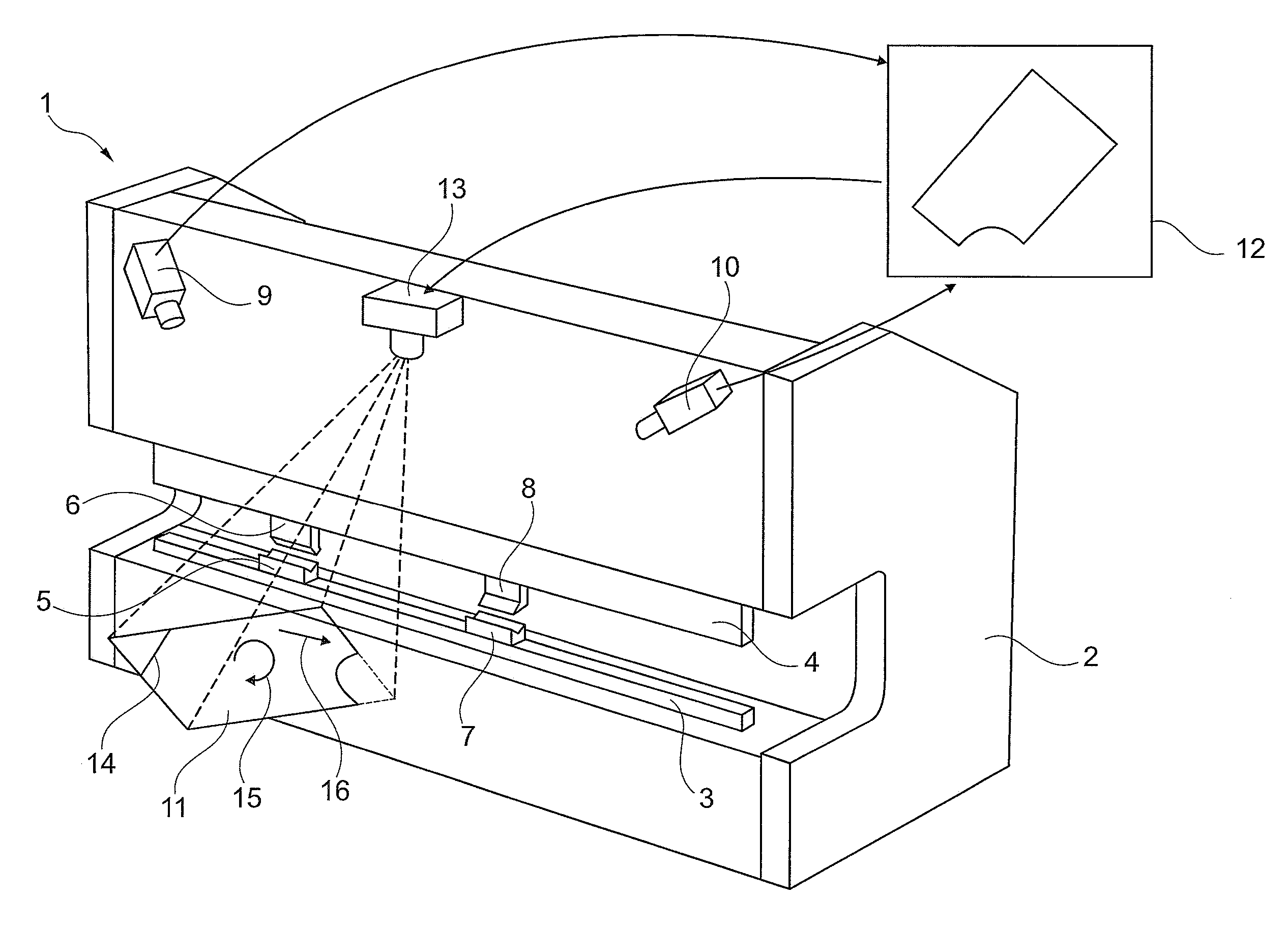
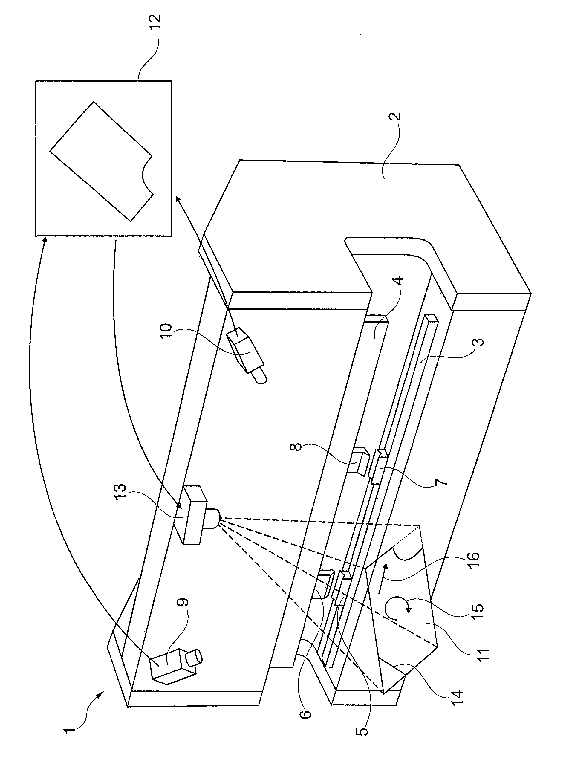
[0039]FIG. 1 shows a press brake 1. This press brake 1 has a frame 2 with a stationary lower beam 3 and a movable upper beam 4. The lower beam 3 and movable upper beam 4 comprise two sets of tools 5, 6 and 7, 8 for performing two separate machining operations.

[0040]The press brake 1 has at the top two camera's 9, 10 which capture a three dimensional image of a metal sheet 11. Based on these images an orientation of the metal sheet 11 relative to the press brake can be determined. This orientation is compared in a controller 12 with a required orientation. As a result the controller controls a projector 13 at the top of the press brake 1, to project images on the metal sheet 11.

[0041]The controller 12 projects with the projector 13 a virtual bending line 14 to indicate to the operator, which part of the metal sheet 11 should be bent. Furthermore an icon 15 for rotating the metal sheet 11 is shown, telling the operator that the sheet 11 should be rotated for a correct orientation. Al...


PUM

PropertyMeasurementUnit
shapeaaaaaaaaaa
lengthaaaaaaaaaa

Abstract

Disclosed is a method for aiding in manual handling of a work piece during machining, which method comprises the steps of: reading a predetermined work plan, comprising a required orientation of the work piece for each machining step of the work plan; detecting the orientation of the work piece; comparing the detected orientation of the work piece with the required orientation; and projecting an indication on the work piece for aiding to manually orient the work piece to the required orientation for the machining step to be performed. Al disclosed is a device for performing the method.

Description

BACKGROUND OF THE INVENTION[0001]Field of the Invention[0002]Method and device for aiding in manual handling of a work piece during machining[0003]The invention relates to a method for aiding in manual handling of a work piece during machining.[0004]Description of Related Art[0005]When using for example a press brake for bending a sheet material, it is sometimes difficult to determine how to orient the work piece to perform the next machining step. A press brake typically is provided with several tools next to each other for performing the different machining steps. A first tool could cause the sheet material to bend upwardly, while a second tool could cause the sheet material to bend downwardly. Such choices are made depending on the intermediate shape of the work piece and the abilities of the tools and restrictions of the press brake.[0006]Orienting the work piece for a next machining step requires spatial awareness of the operator, which sometimes is only obtained after a number...

Claims


Application Information

Patent Timeline
Patent Type & Authority Patents(United States)
IPC IPC(8): B23Q17/22B23Q17/24G05B19/4097
CPCB23Q17/2414B23Q17/22B23Q17/2428G05B19/4097G05B2219/31048G05B2219/32001G05B2219/45143G05B2219/45234Y02P90/04Y10T29/49764Y10T29/49766Y10T29/49769Y10T29/49771Y10T29/49778Y10T29/53013Y10T29/53087Y02P90/02
Inventor WIELENS, PETER HERMANUS GERHARDUSTIELENBURG, NIELSKOK, ALEXANDER STEFAN
Owner NIVORA IP
Learn More