
Input device with force sensing and haptic response

a technology of input device and force sensing, applied in the field of input devices, can solve the problems of limiting the flexibility of the proximity sensor device to function as an input device, limiting the ability of sensors to use, and limiting the accuracy of the application of the proximity sensor when estimating the applied force using these techniques, etc., to facilitate the actuation of piezoelectric materials, facilitate the effect of force determination, and facilitate the improvement of the performance of the input devi

Active Publication Date: 2017-01-31
SYNAPTICS INC
View PDF94 Cites 41 Cited by
  • Summary
  • Abstract
  • Description
  • Claims
  • Application Information

AI Technical Summary

Benefits of technology

The patent describes devices and methods that improve input device performance by using a special arrangement of electrodes on a piezoelectric material. These electrodes, along with a spacing element and a transmission element, help determine the force applied to the material. The devices can also provide haptic feedback to the user, making it easier to interact with the device. Overall, this arrangement simplifies force sensing and haptic response, resulting in a more cost-effective and complex input device.

Problems solved by technology

Unfortunately, some implementations of these proximity sensors have had limited accuracy when estimating applied force using these techniques.
Because of questionable accuracy, such sensors have typically had limited ability to use such determined force as a basis for determining user input.
This limits the flexibility of the proximity sensor device to function as an input device.

Method used


Image

  • Input device with force sensing and haptic response
  • Input device with force sensing and haptic response
  • Input device with force sensing and haptic response

Examples


Embodiment Construction

[0019]The following detailed description is merely exemplary in nature and is not intended to limit the invention or the application and uses of the invention. Furthermore, there is no intention to be bound by any expressed or implied theory presented in the preceding technical field, background, brief summary or the following detailed description.

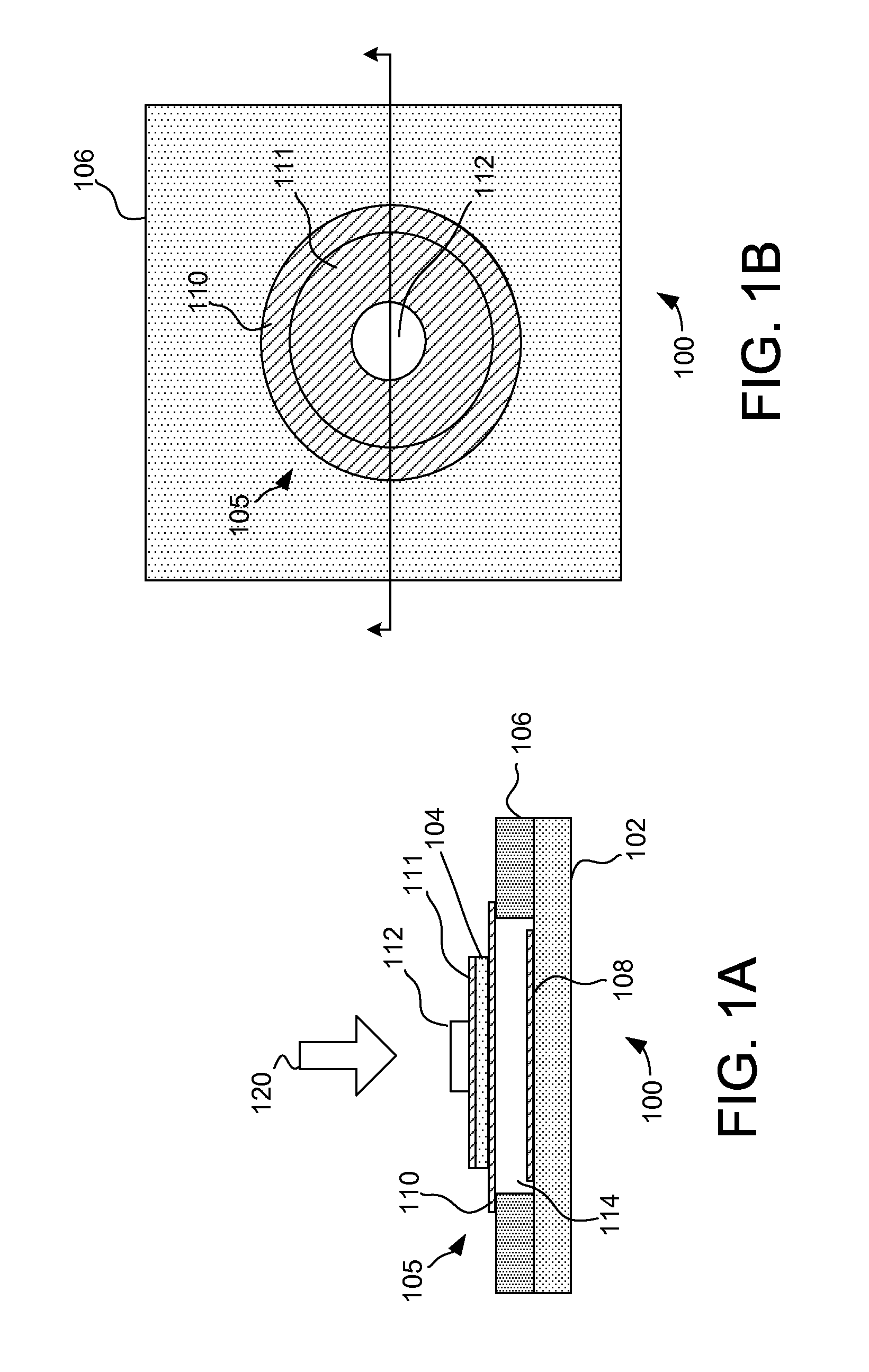
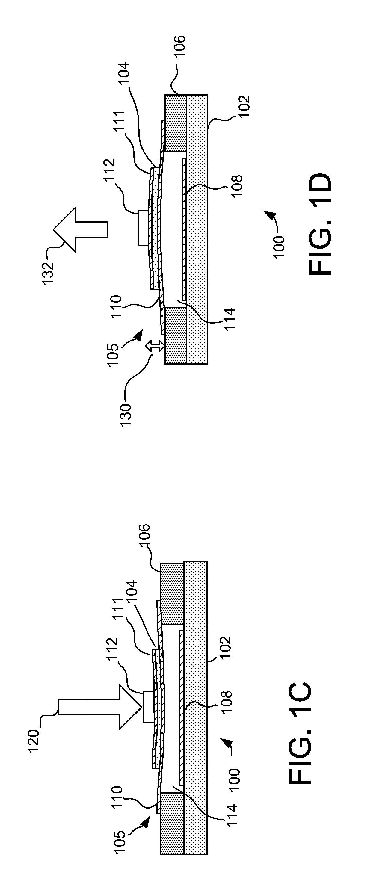
[0020]Devices and methods are provided that facilitate improved input device performance. Specifically, the devices and methods provide an input device with force sensing and haptic feedback in a cost effective and efficient manner. Turning now to FIGS. 1A-1F, cross-sectional and partial top views of an input device 100 is illustrated. The input device 100 includes a first substrate 102, a spacing element 106, a first electrode 108, a transmission element 112 and a piezoelectric assembly 105 comprising a piezoelectric material 104, a second electrode 110, and a third electrode 111. The spacing element 106 includes a spacing 114 that is pos...


PUM


Abstract

Devices and methods are provided that facilitate improved input device performance. The devices and methods utilize a first electrode disposed on a first substrate, a second electrode coupled to a first side of a piezoelectric material and a third electrode coupled to a second side of the piezoelectric material. The second electrode and the third electrode are configured to facilitate actuation of the piezoelectric material, while the first electrode and the second electrode define at least part of a variable capacitance that facilitates force determination. A spacing element is coupled to the first substrate and defines a spacing between the first electrode and the second electrode. A transmission element is coupled to the third electrode and configured such that a force biasing the transmission element causes the second electrode to deflect relative to the first electrode, thus changing the variable capacitance.

Description

FIELD OF THE INVENTION[0001]This invention generally relates to electronic devices, and more specifically relates to input devices, such as proximity sensor devices and force sensor devices.BACKGROUND OF THE INVENTION[0002]Proximity sensor devices (also commonly called touch sensor devices) are widely used in a variety of electronic systems. A proximity sensor device typically includes a sensing region, often demarked by a surface, in which input objects can be detected. Example input objects include fingers, styli, and the like. The proximity sensor device can utilize one or more sensors based on capacitive, resistive, inductive, optical, acoustic and / or other technology. Further, the proximity sensor device may determine the presence, location and / or motion of a single input object in the sensing region, or of multiple input objects simultaneously in the sensor region.[0003]The proximity sensor device can be used to enable control of an associated electronic system. For example, p...

Claims


Application Information

Patent Timeline
Patent Type & Authority Patents(United States)
IPC IPC(8): G06F3/01G06F3/0354G06F3/041G06F3/044
CPCG06F3/044G06F3/016G06F2203/04105G06F3/0445G06F3/0447
Inventor SCHEDIWY, RICHARD R.
Owner SYNAPTICS INC
Learn More