Current transmission device for charging electrical energy stores of vehicles at overhead charging stations

a technology of current transmission device and charging station, which is applied in the direction of charging station, battery/cell propulsion, transportation and packaging, etc., can solve the problem that the appearance of overhead lines is often perceived as unaestheti

Active Publication Date: 2017-01-24
SCHUNK BAHN UND INDTECHN
View PDF45 Cites 1 Cited by
  • Summary
  • Abstract
  • Description
  • Claims
  • Application Information

AI Technical Summary

Benefits of technology

The invention is a current transmission device for charging electric vehicles, particularly those used in public transportation. The device is designed to be compact and simple, and to make quick and secure electrical contact with the charging station for the vehicle. It is also robust against high mechanical stresses. The device uses an articulated arm system to deploy and retract the contact elements, which is formed as a low-weight, simple, and low-maintenance solution. The contact elements have a large circumference to allow the vehicle to position itself below the charging device, even if there is a slight lane offset or obstacles to be avoided. The individual contact elements can also be moved to ensure secure contacting, even if there are variations in production or assembly tolerances, or if the vehicle is in a vertically inclined position.

Problems solved by technology

Transportation systems of this kind require substantial investments in the traffic infrastructure to be provided, in particular in terms of the costs for installation and maintenance of the overhead line system.
In addition to this dependence on rails and lanes, the appearance of overhead lines is often perceived as unaesthetic, especially in the area of the city center.
However, on the one hand, these means of transportation require a charging infrastructure including charging stations at which the accumulators of the electric vehicles can be stationarily charged at certain distances.

Method used


Image

  • Current transmission device for charging electrical energy stores of vehicles at overhead charging stations
  • Current transmission device for charging electrical energy stores of vehicles at overhead charging stations
  • Current transmission device for charging electrical energy stores of vehicles at overhead charging stations

Examples


Embodiment Construction

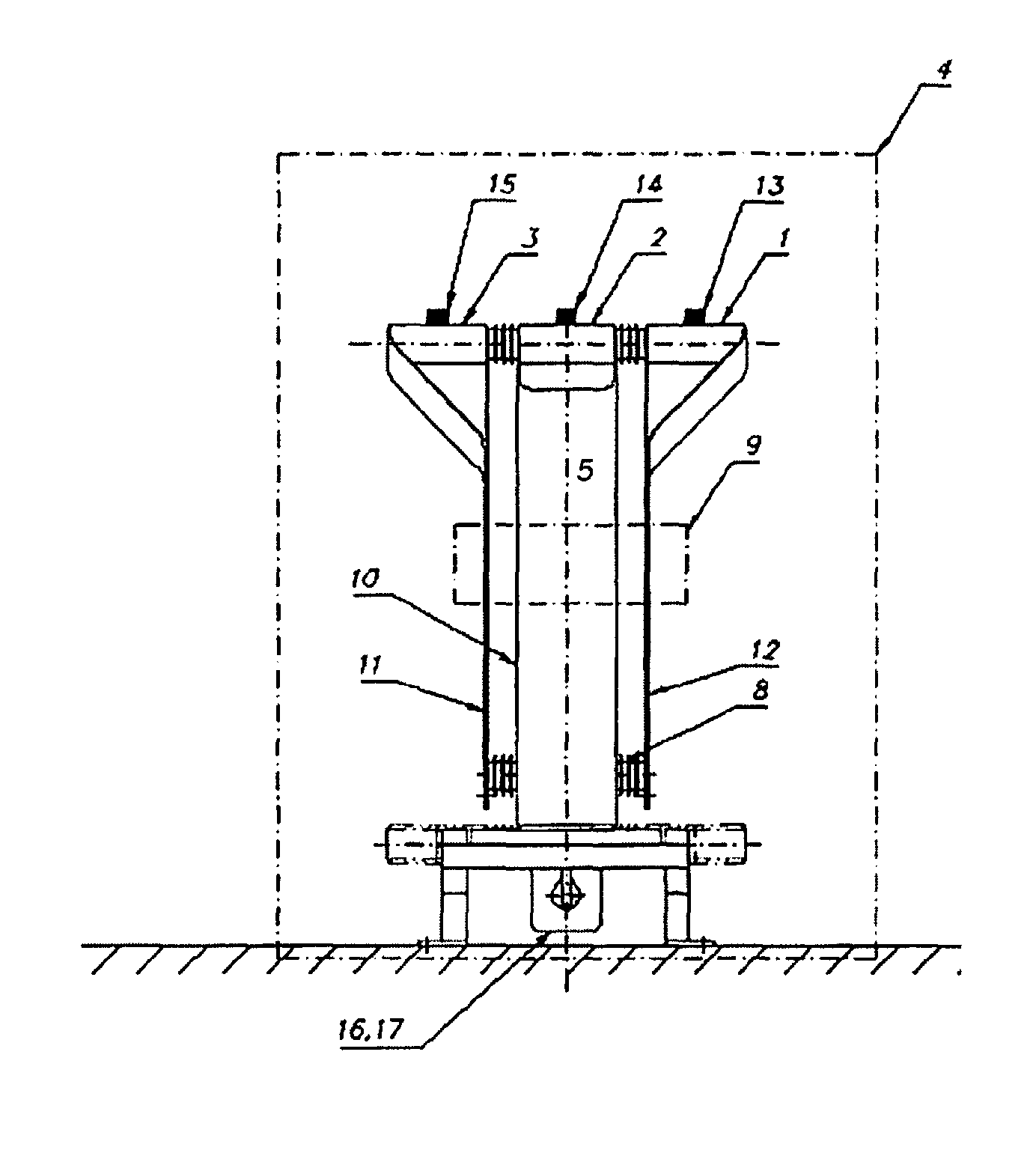
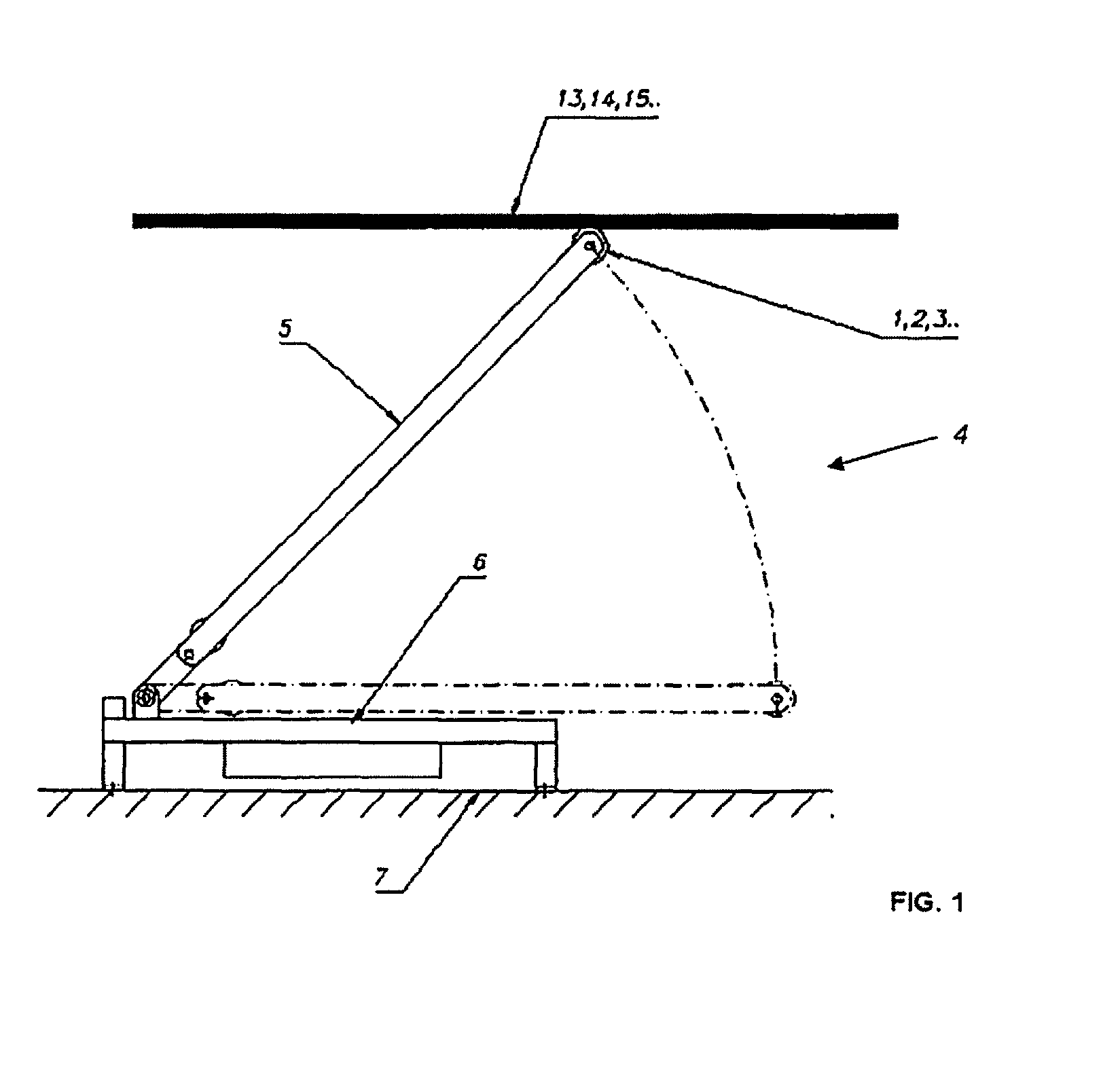
[0022]FIG, 1 shows a schematic illustration of the structure of the charge current collector 4 according to the invention. In the illustrated embodiment, the charge current collector is formed as a one-arm articulated arm system with an articulated arm 5. The articulated arm 5 is pivotably attached to a base frame 6 which is permanently mounted on the roof surface of an electric vehicle 7. In the retracted state, the articulated arm 5 rests on the base frame 6 parallel to the roof surface. On the end of the articulated arm 5 facing away from the pivot bearing, three contact elements 1, 2, 3 are arranged lying next to each other on an axis extending vertically to the driving direction. By pivoting open the articulated arm 5, the contact elements 1, 2, 3 can be brought into contact with the current-supplying contact surfaces 13, 14, 15 of a charging station which are arranged above the vehicle 7. In this context, current-supplying contact surfaces 13, 14, 15 are to be understood to al...


PUM


Abstract

A vehicle-side current transmission device (4) for the stationary charging of electrical energy stores of vehicles (7) at charging stations includes current-supplying contact surfaces (13, 14, 14) arranged above the vehicle (7), wherein a charge current collector (4) formed as an articulated arm system (4) is multi-pole and has, for making stationary contact with the current-supplying contact surfaces (13, 14, 15), at least two isolated electrical contact elements (1, 2, 3) that transmit different electrical phases. The collector enables electrical contacts by a single current collector, which transmit different electrical phases while grounding the vehicle. The articulated arm system allows for an especially compact design with low weight, and enables the vehicle driver to simply position the vehicle below the overhead charging station, coupled with a reliable contacting of the contact surfaces.

Description

FIELD OF THE INVENTION[0001]The invention relates to a vehicle-side current transmission device for the stationary charging of electrical energy stores of vehicles at charging stations by means of energy-supplying contact surfaces arranged above the vehicle.BACKGROUND OF THE INVENTION[0002]Transportation systems are generally known from the state of the art in which electrically driven vehicles are supplied with electrical energy via overhead lines. Means of transportation of this kind are used in particular in public local passenger transport as rail-bound trolley cars or as lane-bound trolley busses. For supplying traction current, a current collector with electrical sliding contacts is in constant sliding contact with the current-carrying overhead wire hanging above the vehicle. Transportation systems of this kind require substantial investments in the traffic infrastructure to be provided, in particular in terms of the costs for installation and maintenance of the overhead line ...

Claims


Application Information

Patent Timeline
IPC IPC(8): B60L11/00B60L11/18
CPCB60L11/1816B60L11/18B60L11/185B60L11/1818B60L2200/26Y02T10/7005Y02T10/7072Y02T90/121Y02T90/128Y02T90/14B60L53/16B60L53/11B60L50/60Y02T10/70Y02T90/12B60L53/14
Inventor SANTNER, JOSEF
Owner SCHUNK BAHN UND INDTECHN
Why Eureka
Try Eureka