Robotic mechanism with two degrees of freedom

a technology of robotic actuators and actuation mechanisms, applied in the direction of manipulators, joints, manufacturing tools, etc., can solve the problems of large joint weight, low design efficiency, and high cost of strength and stiffness, and achieve the effects of preventing joint separation, substantial stiffness against bending or distortion, and enduring high bending and twisting torqu

Active Publication Date: 2017-01-24
TECHNION RES & DEV FOUND LTD
View PDF4 Cites 18 Cited by
  • Summary
  • Abstract
  • Description
  • Claims
  • Application Information

AI Technical Summary

Benefits of technology

[0009]The two cylinders can be rotated relative to the base elements of the link mechanism using motors driven directly onto the cylinders, or through an external gear. Relative rotation between the two cylinders results in a change of the inclination angle between the axial centerlines of the upper and lower cylinders as they rotate. On the other hand, simultaneous synchronized rotation of both cylinders in the same direction and at the same speed, causes them to act as a single solid unit, such that the inclined link mechanism rotates around the axis through one of the cylinders, with the other axis inclined at the angle at which the output platform is oriented relative to the base. Consequently, the azimuthal orientation of the inclination of the link mechanism can be rotated 0-360° in space. A combination of both of these rotation modes provides the ability to amend the pose of the robotic link mechanism within the envelope made available by the angle of inclination of the two cylinders. Thus, the inclination angle of the link mechanism is achieved by rotating one the cylinder with respect to the other while the orientation of the inclined cylinder is achieved by a synchronized rotation of both cylinders.
[0011]The function of the flexible passive joint between the base elements is to hold the base elements together and prevent mutual rotation of the base elements, while allowing the cylinders captured between them to change their mutual orientations. Further implementations of the robotic link mechanism of the present disclosure can achieve this aim by externally clamping the cylinders rotatably to the base elements and the cylinders to each other. This can be achieved by the use of clamping rings mounted on lip-like flanges formed at the ends of the cylinders and on the base elements, such that they clamp adjacent lips together, preventing their separation, but allowing them to mutually rotate. Thus, the cylinders can be attached to their base elements and the cylinders to each other, without impeding their relative rotation. An additional element must be provided to prevent the base elements from rotating relative to each other. These embodiments have the advantage of leaving a large clear passageway along the axis of the device, such as could be useful for many industrial and medical applications.
[0012]The only rotating parts of the link mechanism are the inclined cylinders, while the base elements of the device are fixed, and act as supports for the rotation motors and associated gears. This kinematic arrangement results in a backbone composed of a passive universal joint, (at least for those implementations that incorporating the centrally located universal joint) which is supported and actuated by the cylindrical structure that serves as an active exoskeleton. Consequently, this mechanical design can withstand high bending and twisting torques because bending torques resulting from self-weight and external loads are handled by the exoskeleton structure, at the inclined plane connecting the two cylinders and at the contact planes of the cylinders with the mechanism base elements. These cylindrical elements have substantial stiffness against bending or distortion.
[0015](i) the rotation of the cylinders using the motors needs only to overcome the sliding frictional forces, which are lower by approximately one order of magnitude (the coefficient of friction) than the gravitational forces resulting from the weight of a sturdy long arm and its payload, which are handled in this device by the exoskeleton structure, and(ii) the exoskeleton structure, which handles the self weight of the entire arm and payload, can have a much higher stiffness / weight ratio than a conventional articulated arm.
[0018]In such a mechanism, the passive flexible joint should be connected to the base elements such that it prevents the base elements from separating, thereby confining the first and second cylinders between the base elements. Additionally, the motors should be adapted to generate relative rotation between the two cylinders, such that the axes of the cylinders undergo mutual change in inclination as the cylinders rotate relative to each other. In such mechanisms, a combination of rotation modes of the cylinders thus enables adjustment of the pose of one of the base elements relative the other, within the envelope made available by the angles of inclination of the obliquely formed end surfaces of the two cylinders. Furthermore, rotation of one of the cylinders with respect to the other defines a combination of the inclination and the azimuthal orientation of one of the cylinder axes relative to the other.
[0022]According to further exemplary implementations, the passive flexible joint connecting the first and second base elements may be any one of a mechanical universal joint, a flexible shaft, a spiral spring element, and a pair of half-shafts connected by a flexible polymer central section. Alternatively, it may be an inverted universal joint assembly external to the axis of the cylinders, such that the axis can be free of impediments.

Problems solved by technology

The maneuverability inherent in these types of mechanical structures and their compliance, i.e., their ability to conform to environmental constraints, allow them to overcome obstacles of significant complexity compared to conventional robots; hence they have become a challenge for robotic mechanism designers.
The universal joint, which was installed on the outside, rendered the joint relatively bulky.
This allowed for a more compact design, but came at the cost of strength and stiffness (backlash).
Other known designs use cable / tendon actuation systems for driving the robot, yet these designs are somewhat cumbersome and require quite a large external driving system, as shown in the article by R. Cieslak et al, “Elephant trunk type elastic manipulator—A tool for bulk and liquid materials transportation” published in Robotica, vol.
One of the biggest challenges in the design of a hyper-redundant long manipulator is maintaining reasonable dimensions and low self-weight, while not compromising the rigidity of the structure and its accuracy.
Usually, these design criteria are counter-intuitive, since rigidity is usually achieved by use of structures having large physical dimensions and high self-weight, the latter being a particular disadvantage in long robotic manipulator arms.
Many of the prior art robotic arm implementations have these limitations, and involve complex or massive structures to provide the rigidity required by long robotic arms.

Method used


Image

  • Robotic mechanism with two degrees of freedom
  • Robotic mechanism with two degrees of freedom
  • Robotic mechanism with two degrees of freedom

Examples


Embodiment Construction

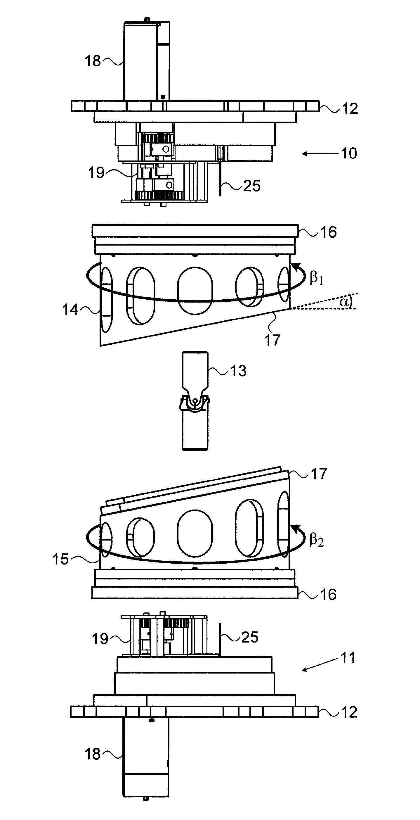
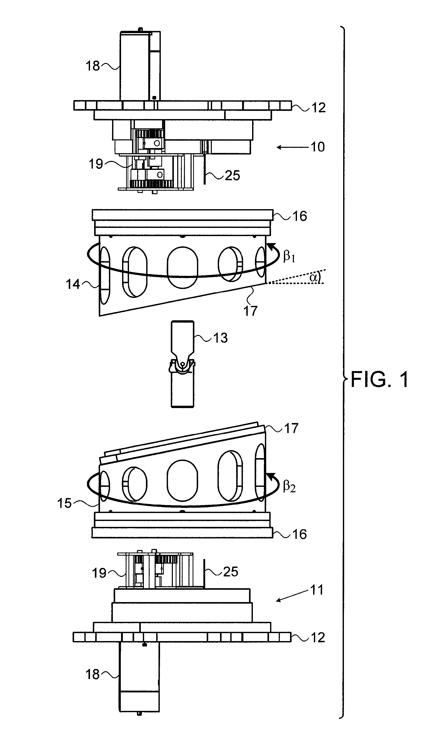
[0043]Reference is now made to FIG. 1 of which illustrates an exploded view of one exemplary implementation of a robotic actuator device having a link mechanism of the type described in the present disclosure. The device comprises a pair of base elements 10, 11, shown constructed on base flanges 12, the two base elements 10, 11, representing what is termed in common parlance as the static base and the actuated robotic platform of the robotic mechanism. Since the device is symmetric, the definition of which base element is the “static” base and which is the actuated output platform is nominal, since either end can be considered to be able to fulfill either function, depending on the specific use to which the robotic link is put. The base elements are connected together by a flexible joint 13 shown in FIG. 1 as a mechanical universal joint providing two degrees of freedom, though it could be any other form of flexible shaft. The universal joint is connected rigidly at its ends to the ...


PUM


Abstract

A robotic link mechanism comprising a pair of base elements connected by a passive flexible joint, such that flexure of the joint changes the mutual orientation of the base elements. A pair of obliquely truncated cylinders are confined between the base elements such that the obliquely formed end surfaces of the cylinders can rotate in sliding contact with each other, and the other end of each cylinder can rotate in sliding contact with its associated base element. Driving motors are attached to the base elements, each one controlled to rotate the cylinder associated with that base element, such that rotation of at least one of the cylinders causes the base elements to undergo change in their mutual orientation. The mechanism thus has a backbone composed of the passive flexible joint, which is supported and actuated by the oblique truncated cylindrical structure that serves as an active exoskeleton.

Description

CROSS-REFERENCE TO RELATED APPLICATIONS[0001]This application is a U.S. National Phase Application under 35 U.S.C. 371 of International Application No. PCT / IL2012 / 000383, which has an international filing date of Nov. 29, 2012, and which claims the benefit of priority of U.S. Provisional Patent Application No. 61 / 564,454, filed Nov. 29, 2011, the disclosures of which are incorporated herein by reference in their entirety.FIELD OF THE INVENTION[0002]The present invention relates to the field of robotic actuated mechanisms, especially those having a high load lifting capability and light weight, such that they are capable of being stacked end-to-end to provide a hyper-redundant, high flexibility, long robotic arm.BACKGROUND OF THE INVENTION[0003]A redundant robot has at least one more degree of freedom (DOF) than required for it to perform its intended function, in order to compensate for simple constraints, i.e., using an elbow up configuration as compared to an elbow down configurat...

Claims


Application Information

Patent Timeline
Patent Type & Authority Patents(United States)
IPC IPC(8): B25J17/00B25J18/00B25J17/02
CPCB25J17/00B25J17/0275Y10S901/28Y10T74/20329
Inventor WOLF, ALONSALOMON, ODED
Owner TECHNION RES & DEV FOUND LTD
Why Eureka
Try Eureka