
Gradiometer and method of changing an optical path length to directly obtain a value of a gradient of gravity

a gradient and optical path technology, applied in the field of measuring a characteristic of gravity, can solve the problems of difficult gravimeters with such high precision, relatively complex mathematical interferometric analysis, and inconvenient operation, so as to reduce the freefall distance, avoid the need and complexity, and accurate and direct gradient measurement

Inactive Publication Date: 2017-01-17
MICRO G LACOSTE
View PDF6 Cites 0 Cited by
  • Summary
  • Abstract
  • Description
  • Claims
  • Application Information

AI Technical Summary

Benefits of technology

Enables accurate gravity gradient measurement without complex interferometric calculations, achieving high precision and common mode rejection of errors, making the gradiometer more practical and compact for commercial and industrial applications.

Problems solved by technology

The large background of the earth's gravity requires that any direct gravity measurement to detect such subsurface anomalies have a very large dynamic range of parts per billion, otherwise direct gravity measurements will not be useful for locating and detecting such subsurface density anomalies.
It is difficult to make gravimeters with such levels of extremely high precision.
From a practical standpoint, this approach requires a relatively complex mathematical interferometric analysis of the fringes to obtain the gravity values at each location.
The practical difficulty with this approach is that the difference in the number of fringes is typically in the neighborhood of no more than one fringe, when the test masses move over a distance which can be accommodated by a reasonably sized commercial product.
Obtaining an accurate value of the gravity gradient when that value is represented by a single fringe or less than one fringe is very difficult or impossible.
The extent of mathematical processing required is extensive and complex, and the accuracy is compromised.
The greater number of fringes makes the interferometric calculation more reliable and accurate, but nevertheless adds complexity to the mathematical calculations.
Furthermore, the equipment required to impart the initial velocity difference is more complex, as our the requirements for determining when both test masses commence simultaneous freefall.
These practical operational requirements, plus the added complexity in interferometric analysis and calculation, adds to the complexity of previous interferometric gradiometers.

Method used


Image

  • Gradiometer and method of changing an optical path length to directly obtain a value of a gradient of gravity
  • Gradiometer and method of changing an optical path length to directly obtain a value of a gradient of gravity
  • Gradiometer and method of changing an optical path length to directly obtain a value of a gradient of gravity

Examples


Embodiment Construction

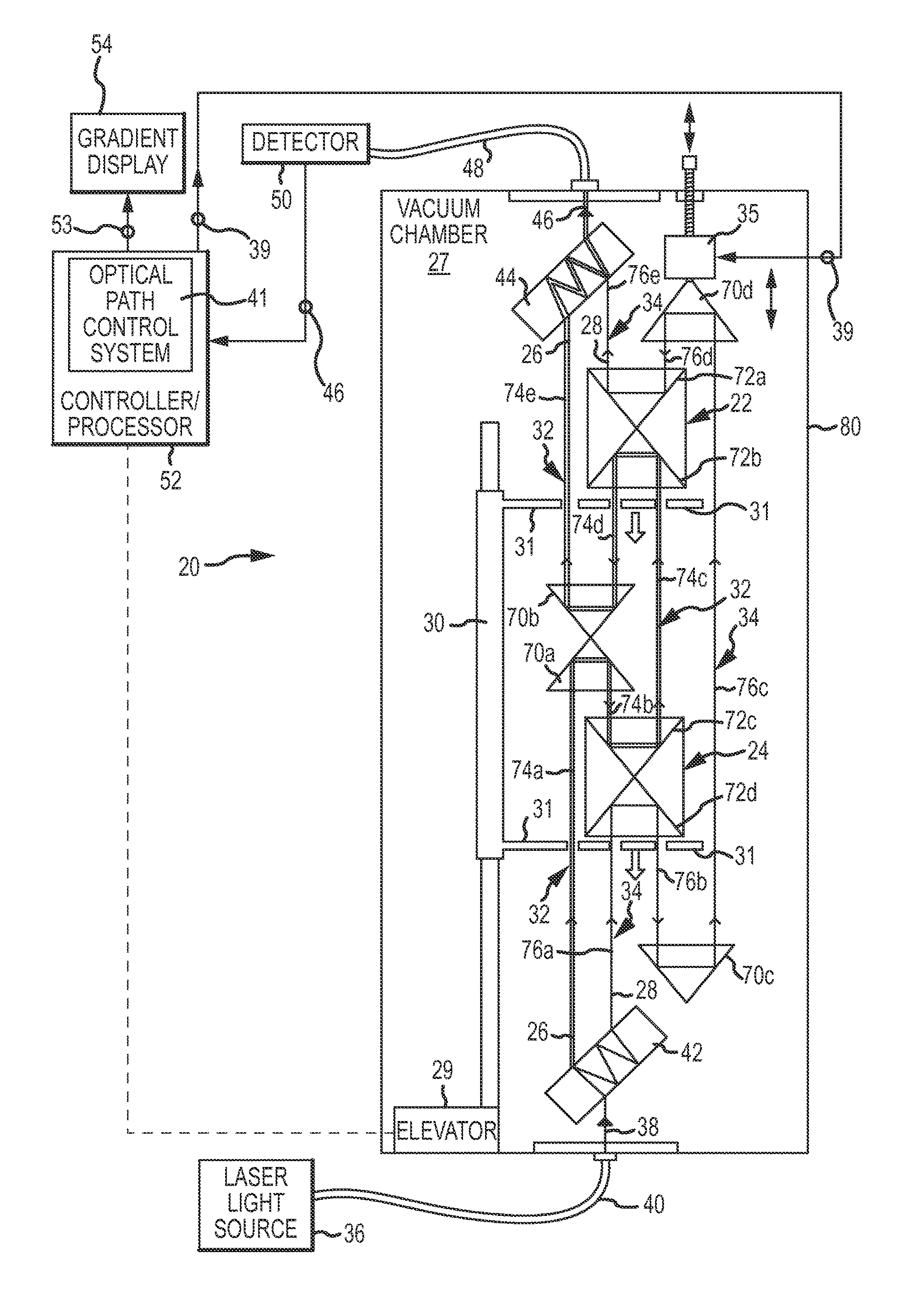
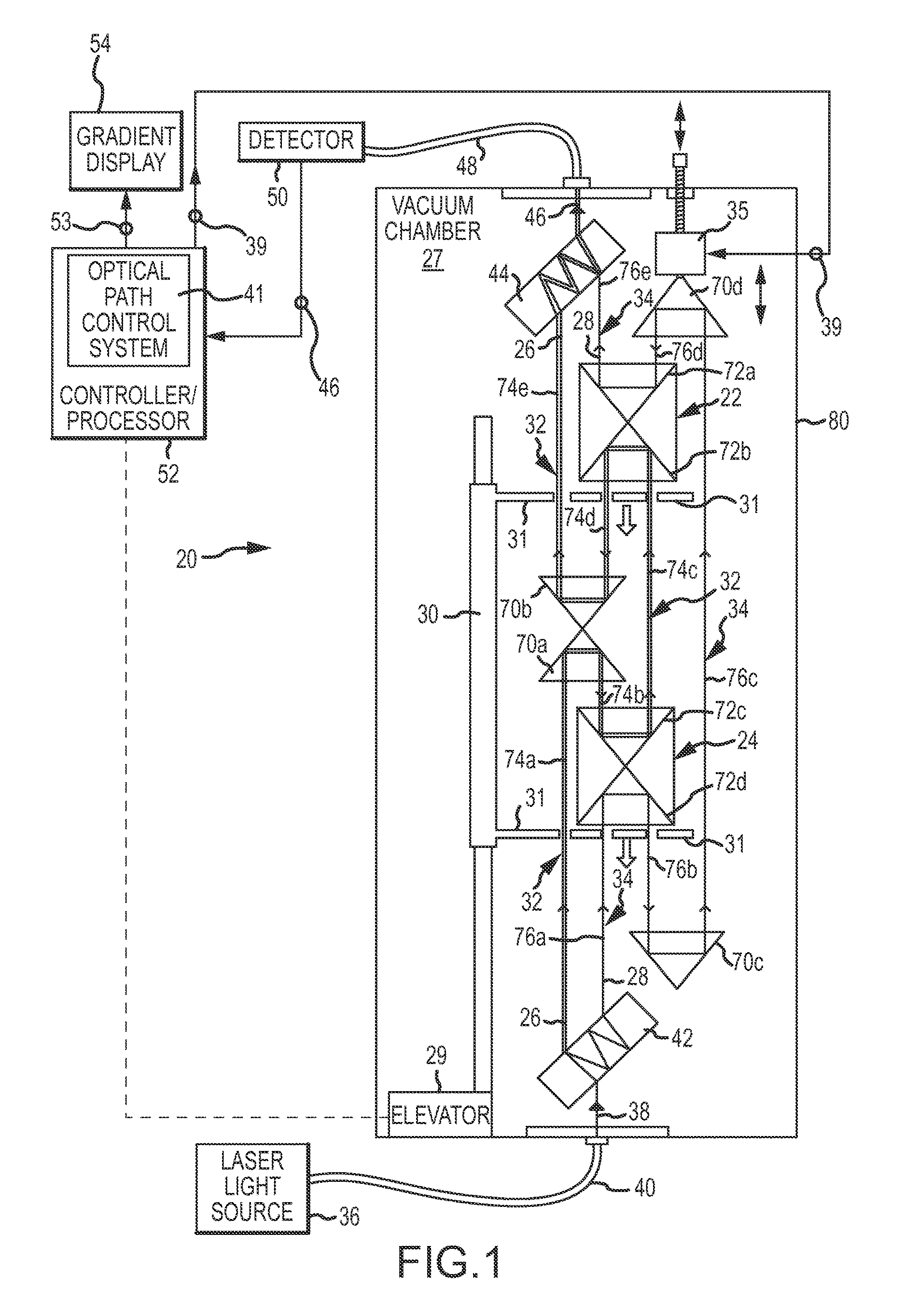
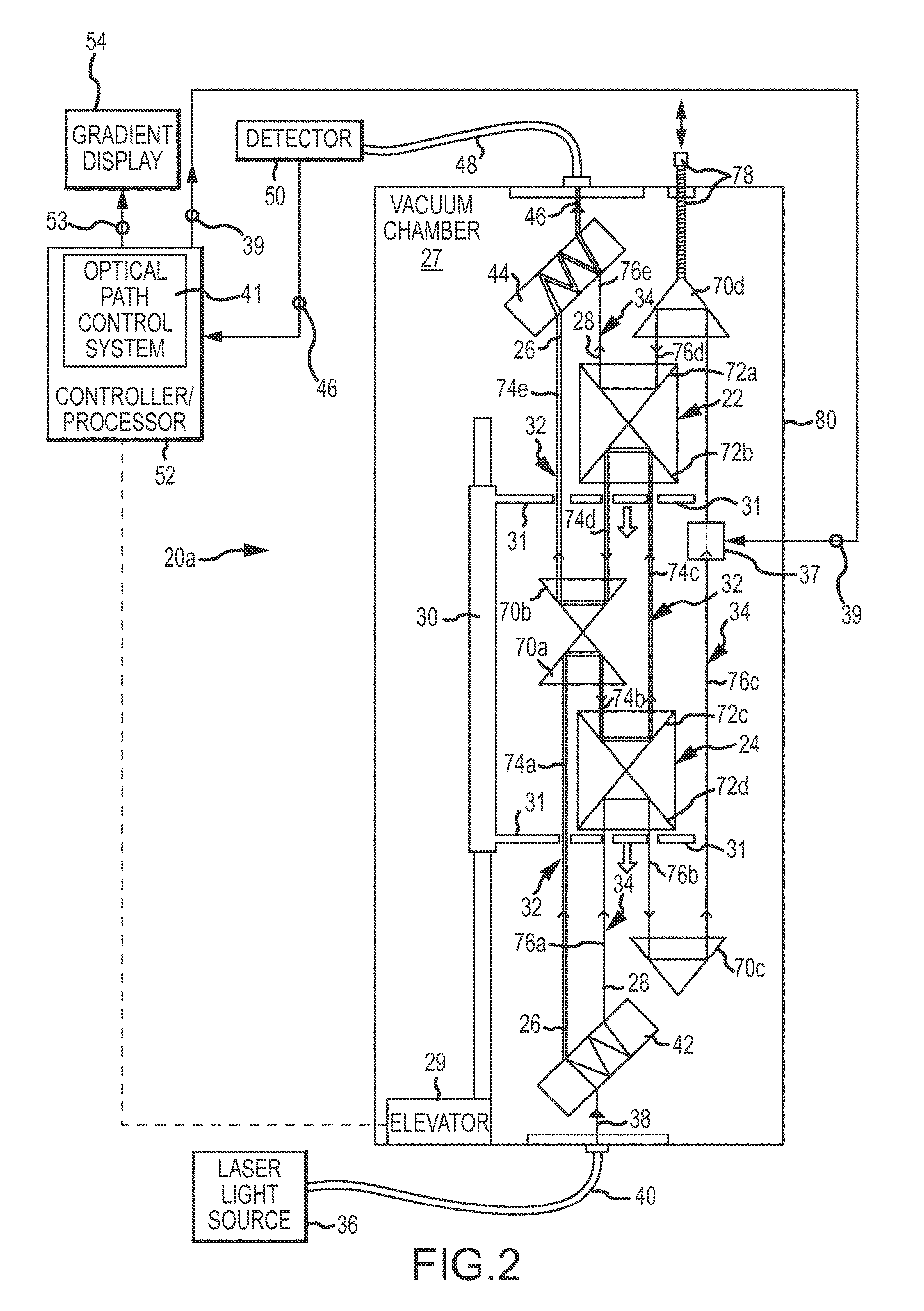
[0026]The present invention is embodied in each of two optical interferometric gradiometers 20 and 20a, shown in FIGS. 1 and 2. The optical gradiometers 20 and 20a are used to measure a gradient of gravity. The gradient of gravity is represented by the relative difference in gravity experienced by two test masses 22 and 24 when they are released to freefall simultaneously only under the influence of gravity. The force of gravity acting on the lower test mass 24 is very slightly greater than the force of gravity acting on the upper test mass 22, since the lower test mass 24 is closer to the center of the earth's mass and therefore experiences a slightly greater gravitational force. A slight difference between the forces of gravity acting on the test masses 22 and 24 constitutes a gradient of gravity which is measured in accordance with the present invention.

[0027]The slightly greater gravity on the lower test mass 24 causes it to experience a slightly greater downward acceleration co...


PUM


Abstract

A gradient of gravity is defined by a change in the optical path length required to maintain equality in optical path lengths of two beam arms which direct light beams to impinge upon and reflect from two freefalling test masses.

Description

CROSS REFERENCE TO RELATED APPLICATION[0001]This is a continuation in part of U.S. patent application Ser. No. 13 / 558,138, which was filed on Jul. 25, 2012 by the inventors hereof, and which was assigned to the assignee hereof. The subject matter of this prior application is fully incorporated herein by this reference. The subject matter of U.S. application Ser. No. 13 / 564,548, also filed by the inventors hereof on Aug. 1, 2012, and also assigned to the assignee hereof, is also incorporated herein by this reference.FIELD OF THE INVENTION[0002]This invention relates to measuring a characteristic of gravity, and more specifically, to a new and improved gradiometer and method which directly measures a change or gradient of gravity without the necessity to perform complex interferometric analysis to calculate the gravity gradient.BACKGROUND OF THE INVENTION[0003]Gravity is the force of inherent natural attraction between two massive bodies. The magnitude of the gravitational force is di...

Claims


Application Information

Patent Timeline
Patent Type & Authority Patents(United States)
IPC IPC(8): G01V7/14G01V7/16G01B9/02
CPCG01V7/14G01B9/02016G01B9/02021G01B9/02045G01V7/16G01B2290/15
Inventor NIEBAUER, TIMOTHY M.KLOPPING, FRED J.BILLSON, RYAN M.
Owner MICRO G LACOSTE
Learn More