
Guided tape applicator

a tape applicator and guide technology, applied in the direction of machine supports, stand/trestles, articles, etc., can solve the problems of manual tape applicators, requiring a significant amount of space, and requiring more expensive tape (per lineal meter of tape), so as to facilitate manual operation and carry a significant amount of the weight of the applicator

Active Publication Date: 2017-01-17
LAMUS TECH INC
View PDF14 Cites 2 Cited by
  • Summary
  • Abstract
  • Description
  • Claims
  • Application Information

AI Technical Summary

Benefits of technology

[0011]It is an objective of the present invention to provide a tape applicator mounting and guiding device that can guide the movement of the tape applicator and facilitate manual operation in that it can carry a significant amount of the weight of the applicator.
[0012]It is an objective of the present invention to permit the use of a Machine roll in manual tape application without the effect of the weight of the heavy Machine tape roll having to be borne by the operator by delivering tape dispensed from a stationery supported tape roll to a tape applicator for applying tape onto an object.

Problems solved by technology

The larger roll also results in more consistent taping performance since most taping problems occurred towards the end or depletion of the roll i.e. when the diameter of the roll has been significantly reduced.
It is estimated 50 percent packaging tape consumers are restricted to Hand rolls since an automatic taping machine is not feasible for their particular operations.
In spite of the economic advantages of the much larger Machine rolls, purchasing and using an automatic taping machine is not justifiable for taping operations that tape less than about 500 cartons a day and automatic taping machines do not lend themselves to intermittent production and / or different sizes of cartons to be taped.
Furthermore automatic taping machines require a conveyor to transport the carton through a stationery tape applicator generally referred to as a tape head that applies tape dispensed from a station tape roll and requires a significant amount of space.
Manual tape applicators as currently know in addition to requiring the more expensive tape (per lineal meter of tape) are also, to a significant degree, limited by the dexterity of the operator for alignment, accuracy and speed of application.

Method used


Image

  • Guided tape applicator
  • Guided tape applicator
  • Guided tape applicator

Examples


Embodiment Construction

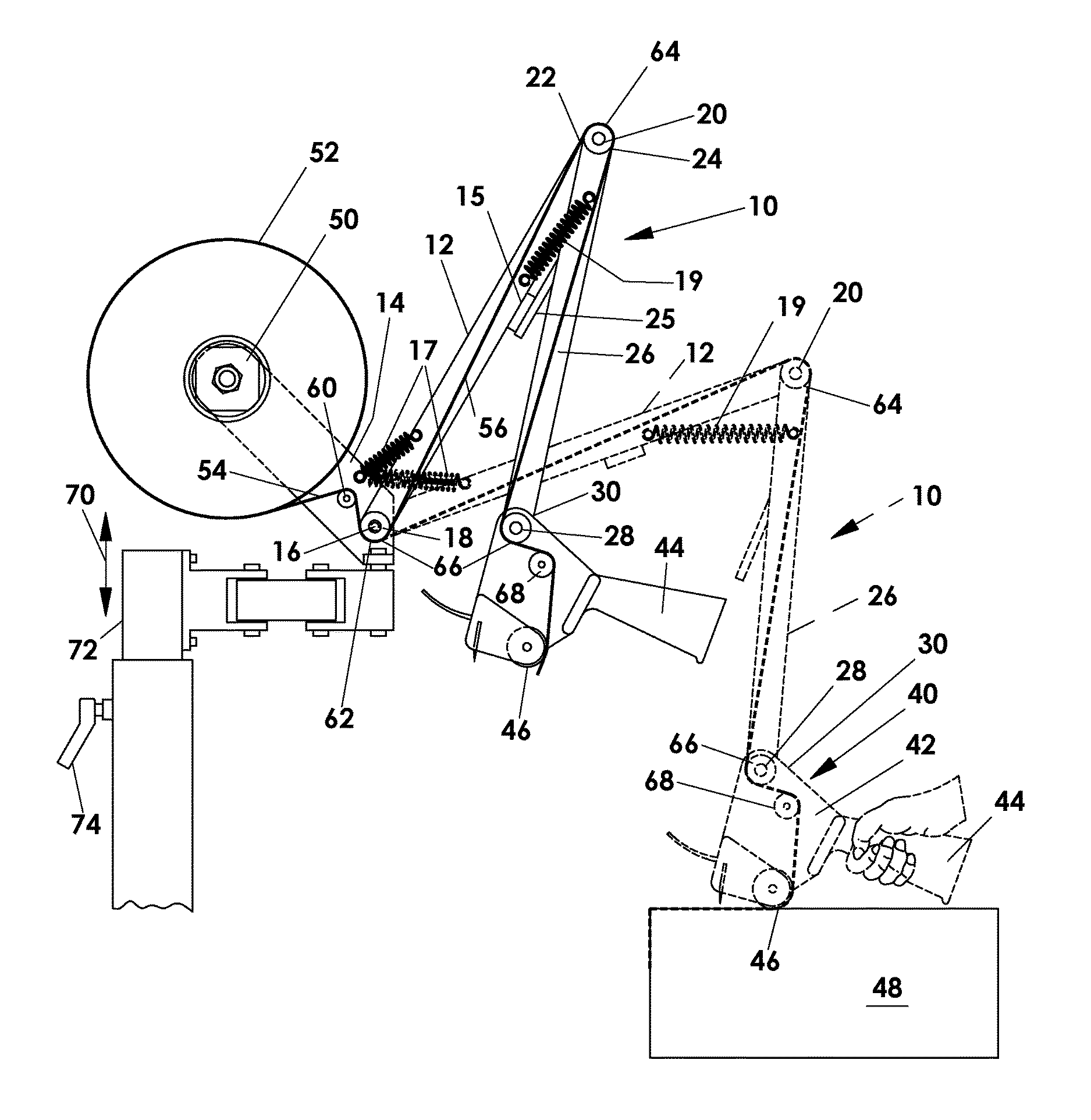
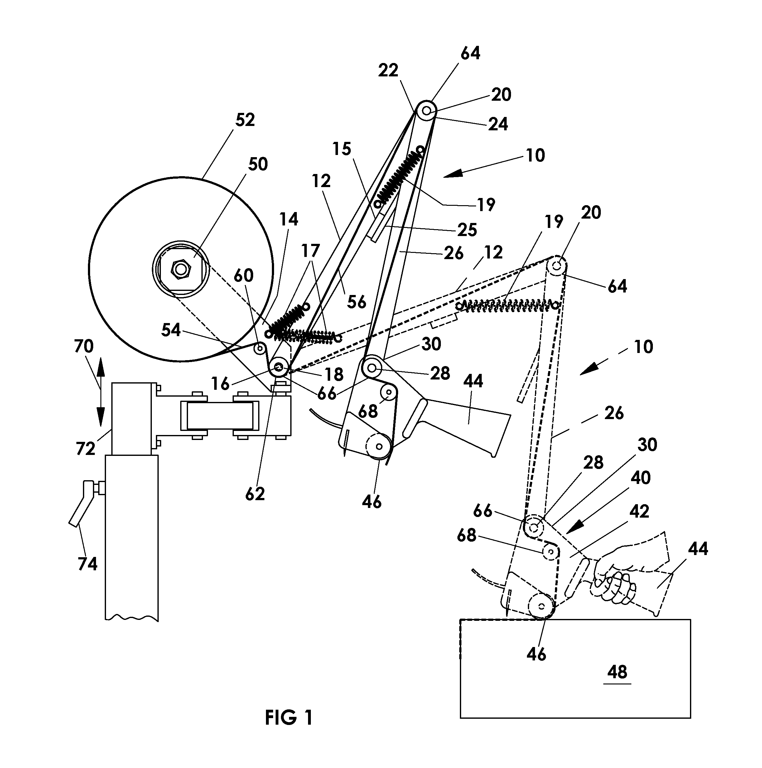
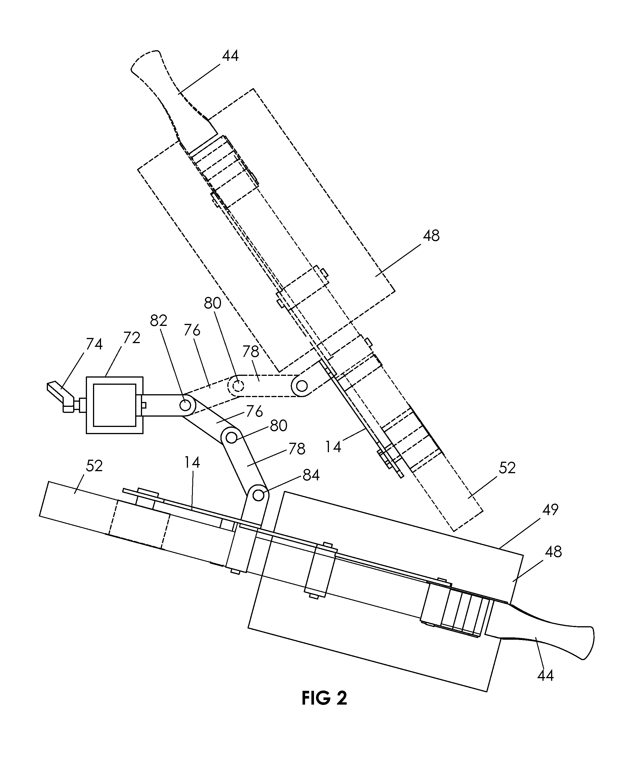
[0023]FIG. 1 shows one embodiment of the present invention with the extensible arm 10 shown in solid lines in a retracted home position and in dash lines in an extended operative position. A first link 12 of the arm 10 is pivotably mounted at to a base 14 adjacent to a first end 16 of the link 12 via a pivotable mounting 18 having a pivotal axis around which the first link may be pivoted relative to the base 14. A pivotable interconnection 20 interconnects a second end 22 of the first link 10 with a first end 24 of a second link 26 of the arm 10 for relative rotational movement of the first and second links around an interconnecting axis formed thereby. Pivotably mounted on a rotatable applicator connection 28 at the free end of the arm 10 as defined in the illustrated embodiment by the second end 30 of the second link 26 is a hand tape applicator in the form of a hand tape applicator 40 the frame 42 of which is rotatably connected at 28 to the second end 30 of link 26. If more link...


PUM


Abstract

A tape applicator system that employs an extendable arm to carry and control the movement of a tape applicator mounted at its moveable or free end. The tape is dispensed from a essentially fixed location remote from the applicator which permits the use of larger roll (Machine rolls) without the necessitating moving the roll as is required in a normal hand operated device. The movement of the tape applicator mounted on the arm is restricted to straight line movement by the linkage of the extendable arm. If desired a parallel linkage mechanism may be used in the arm to maintain the angular orientation of the applicator which is particularly important when the tape applicator is a common tape head normally use in taping machines. Using a constant height system the height of the tape applicator can be maintained constant when in operation.

Description

CROSS REFERENCE TO RELATED APPLICATIONS[0001]Not applicableSTATEMENT REGARDING FEDERALLY SPONSORED RESEARCH OR DEVELOPMENT[0002]Not applicableREFERENCE TO MICROFICHE APPENDIX[0003]Not Applicable.FIELD OF INVENTION[0004]The present invention relates to a manual or power assisted device that may be used to facilitate the application of a tape having pressure sensitive adhesive on one face, in a straight line to an object.BACKGROUND OF THE PRESENT INVENTION[0005]The use of pressure sensitive tape is and has been for many years very common in the packaging industries. The tape being applied is usually dispensed from a tape roll. There are two main categories of tape roll sizes available, namely;[0006]1. For use in manual tape application with a tape dispenser or hand applicator which is restricted in the size and weight as required for ease of handling are generally classified as “Hand rolls” and have a roll size that will usually provide about 100 meters tape length[0007]2. For automat...

Claims


Application Information

Patent Timeline
Patent Type & Authority Patents(United States)
IPC IPC(8): B65H35/00
CPCB65H35/0033F16M2200/061F16M2200/063Y10T156/1788Y10T156/1795F16M11/046F16M11/048F16M11/2014F16M11/24
Inventor LAM, JOE AUGUSTINE S. T.
Owner LAMUS TECH INC
Learn More