
Marking line detection system and marking line detection method of a distant road surface area

a detection system and marking technology, applied in the direction of instruments, ways, images, etc., can solve the problem of incorrect marking line detection processing, and achieve the effect of increasing the detection accuracy of a distant marking lin

Active Publication Date: 2017-01-03
TOYOTA JIDOSHA KK
View PDF20 Cites 26 Cited by
  • Summary
  • Abstract
  • Description
  • Claims
  • Application Information

AI Technical Summary

Benefits of technology

The present invention provides a system and method to detect marking lines on a road surface without having to estimate the shape of the road surface or detect the marking line sequentially. This increases the detection accuracy of marking lines that are far away from the vehicle. This system and method reduce the likelihood of incorrect detection, reducing the processing load and time required.

Problems solved by technology

In the related art, when the road surface shape cannot be estimated successfully, there is a possibility that the marking line detection processing is performed for an incorrect area.

Method used


Image

  • Marking line detection system and marking line detection method of a distant road surface area
  • Marking line detection system and marking line detection method of a distant road surface area
  • Marking line detection system and marking line detection method of a distant road surface area

Examples


embodiment

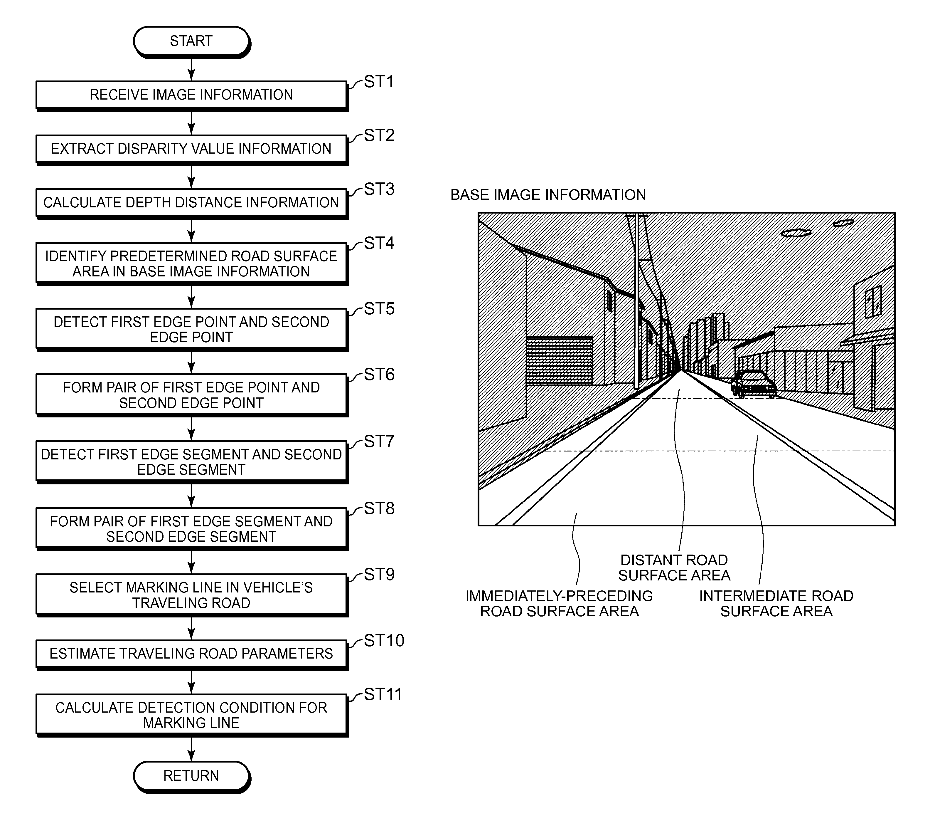
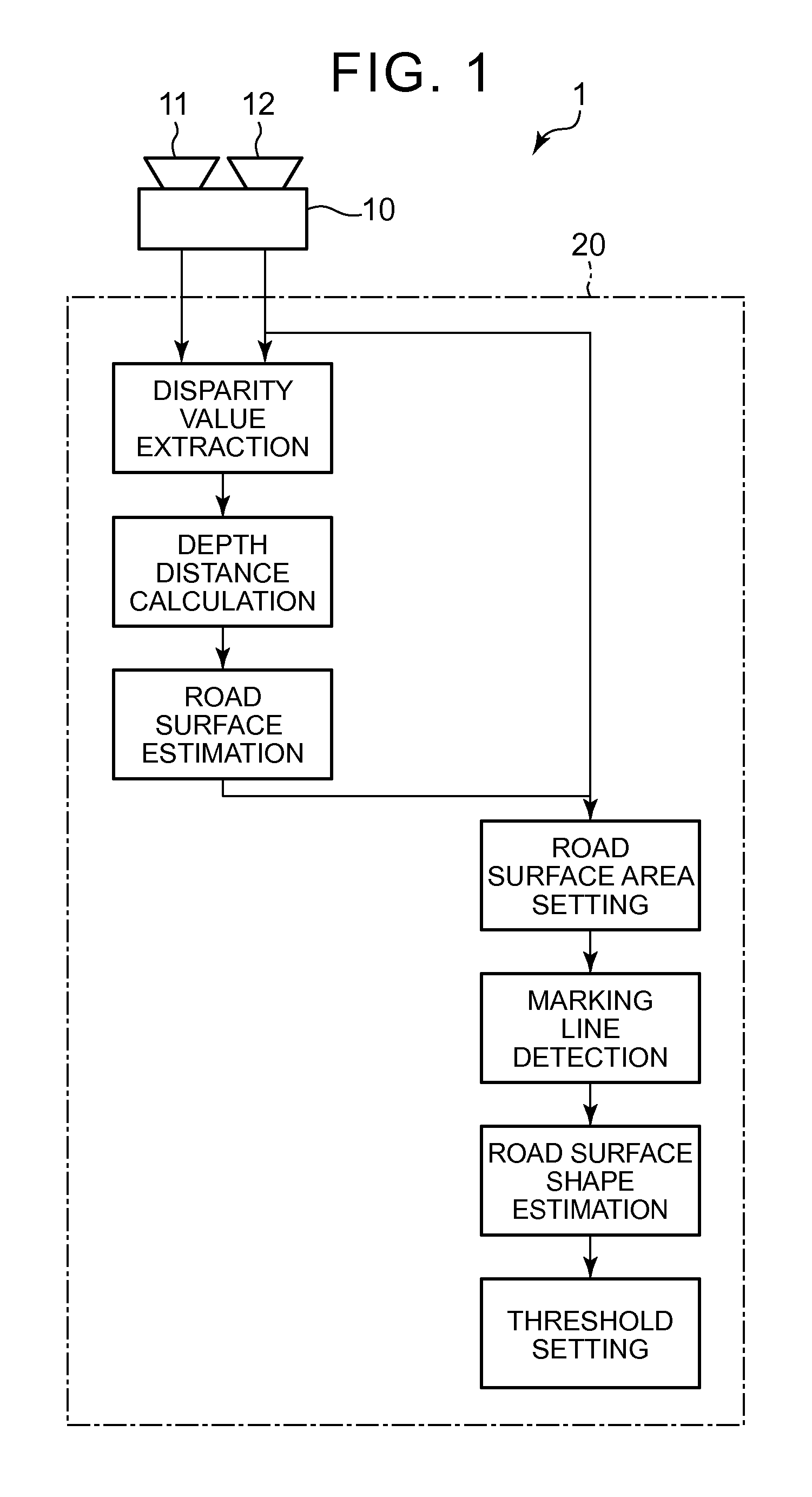
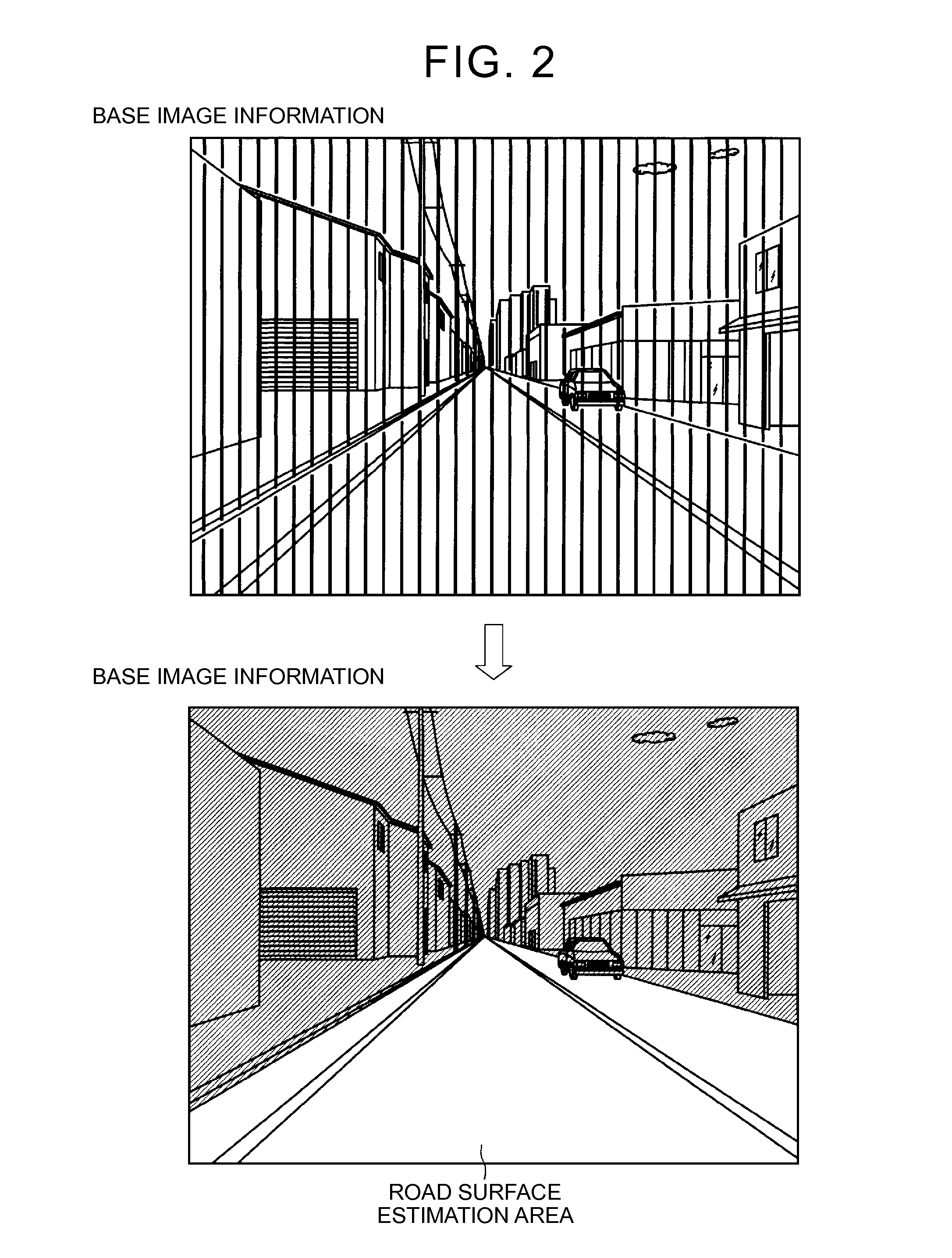
[0028]An embodiment of the marking line detection system and the marking line detection method of the present invention are described with reference to FIG. 1 to FIG. 11.

[0029]FIG. 1 is a diagram showing a marking line detection system 1 in this embodiment. This marking line detection system 1 detects a marking line based on the acquired surrounding information on the vehicle. A marking line in this embodiment refers to a lane boundary line, usually white or yellow in color, on the road surface around the vehicle.

[0030]The marking line detection system 1 includes a surrounding information acquisition unit that acquires the surrounding information on the vehicle, a road surface area identification unit that identifies a road surface area based on the acquired surrounding information, and a marking line detection unit that detects a marking line in the identified road surface area.

[0031]The surrounding information acquisition unit acquires the vehicle surrounding information in which ...


PUM


Abstract

A marking line detection system includes an imaging device and an ECU. An information extraction unit of the ECU is configured to extract depth distance information from the imaging device to an imaging object based on image information in an imaging area captured by the imaging device. A road surface area identification unit of the ECU is configured to identify a distant road surface area based on the depth distance information, the distant road surface area being a road surface area that excludes an immediately-preceding road surface area of the vehicle in the image information and is more distant from the vehicle than the immediately-preceding road surface area. A marking line detection unit of the ECU is configured to detect a marking line in the distant road surface area based on image information corresponding to a position of the distant road surface area.

Description

INCORPORATION BY REFERENCE[0001]The disclosure of Japanese Patent Application No. 2014-022838 filed on Feb. 7, 2014 including the specification, drawings and abstract is incorporated herein by reference in its entirety.BACKGROUND OF THE INVENTION[0002]1. Field of the Invention[0003]The present invention relates to a marking line detection system and a marking line detection method.[0004]2. Description of the Related Art[0005]Japanese Patent Application Publication No. 2003-118521 (JP 2003-118521 A) is known as a detection system and a detection method for detecting a marking line on the road surface around a vehicle. Japanese Patent Application Publication No. 2003-118521 (JP 2003-118521 A) discloses a technology that initially sets the white line detection area in a captured image of the road in front of the vehicle as large as possible and, if the road parameters are updated later to reflect the actual road surface shape, sets the white line detection area as small as possible for...

Claims


Application Information

Patent Timeline
Patent Type & Authority Patents(United States)
IPC IPC(8): G06K9/00B60R1/00E01F11/00G06T7/00G08G1/16
CPCG06K9/00798B60R1/00E01F11/00G06T7/0081G06T7/0083G08G1/167G06T2207/10028G06T2207/30256G06T7/11G06T7/12G06V20/588
Inventor TAKEMAE, YOSHINAO
Owner TOYOTA JIDOSHA KK
Learn More