Method for commanding a multi-axis robot and robot for implementing such a method

a multi-axis robot and robot technology, applied in the direction of programmed manipulators, programme control, instruments, etc., can solve the problems of affecting the safety level, the risk of rapid and uncontrolled movement of the part under the effect, and the failure to meet the safety requirements, etc., to achieve effective steering, simple structure, and high safety level

Active Publication Date: 2017-01-03
STAUBLI FAVERGES SA
View PDF10 Cites 4 Cited by
  • Summary
  • Abstract
  • Description
  • Claims
  • Application Information

AI Technical Summary

Benefits of technology

The invention provides a method for safely controlling a multi-axis robot arm, with a simple architecture that allows for effective steering and ensures high safety standards. The method allows the operator to safely move the robot arm manually or stop it in an emergency situation. A validation member is used to confirm safe intervention by the operator, and a security system analyzes movement information and can command the brakes and motor torque off function of the motors safely. The robot arm also includes a brake releasing member connected to the security system and allows for safe selection of the motor associated with the brace to be opened. In summary, the invention provides a reliable and safe way to control and move a multi-axis robot arm.

Problems solved by technology

When the emergency stop is activated and the user needs to release a brake to move a moving part of the robot, there is then a risk of rapid and uncontrolled movement of that part under the effect of gravity, which is dangerous.
This is detrimental to the safety level, since the redundancy introduced by the safe torque off function is then limited, since the switches of one of the branches are no longer neutralized.
These safety requirements are then no longer met.

Method used


Image

  • Method for commanding a multi-axis robot and robot for implementing such a method
  • Method for commanding a multi-axis robot and robot for implementing such a method
  • Method for commanding a multi-axis robot and robot for implementing such a method

Examples


Embodiment Construction

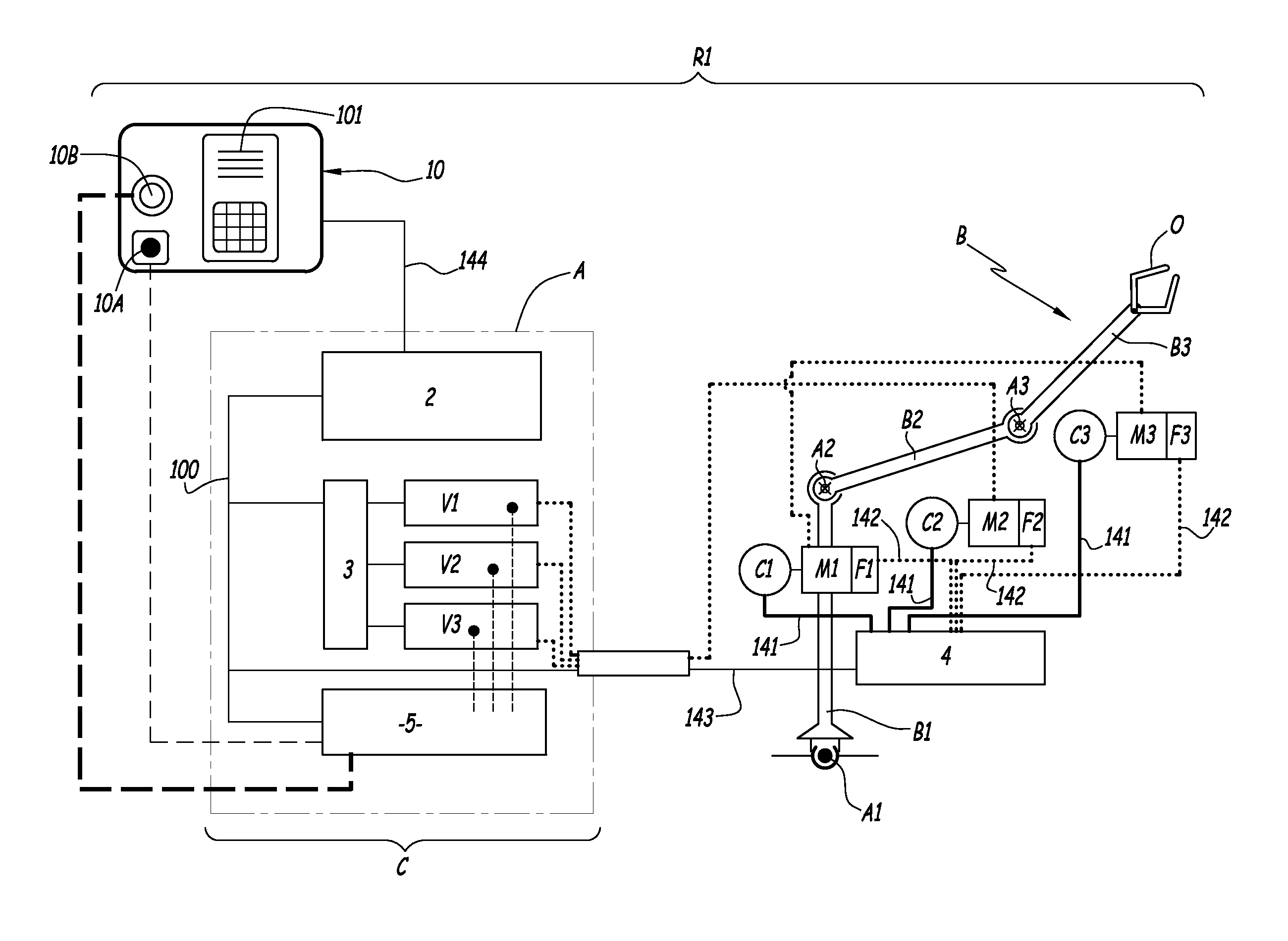
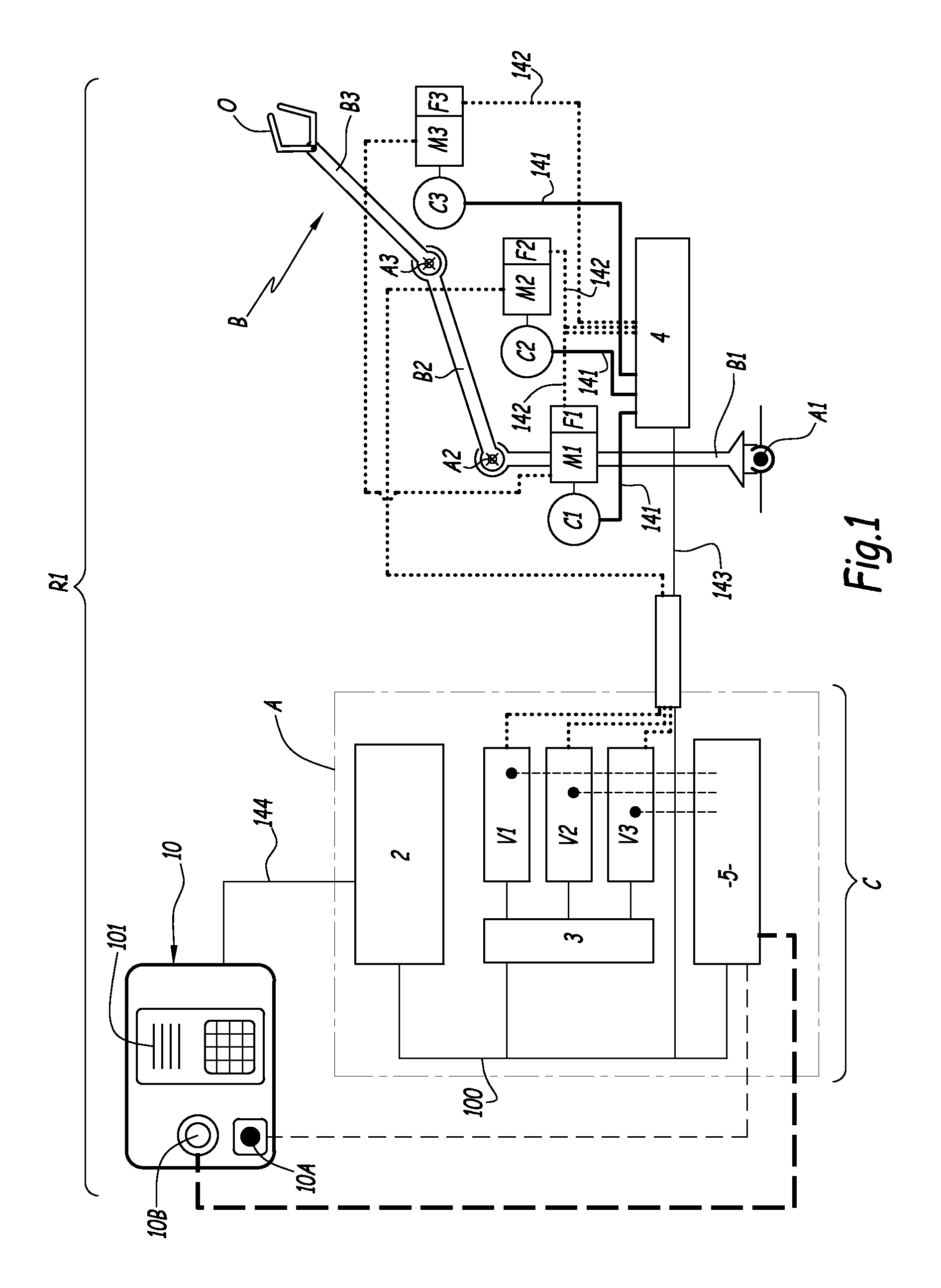
[0063]The arm B of the robot R1 shown in FIG. 1 is provided with three degrees of freedom each commanded by a motor M1, M2 or M3 able to move a moving part B1, B2 or B3 of the robot arm B around a geometric axis A1, A2 and A3, to move a tool O in space.

[0064]The motors M1 to M3 are shown outside the robot arm B in FIG. 1, but in practice, they are distributed inside the robot arm B, near the articulation axes A1, A2 and A3. The motors M1, M2 and M3 are for example brushless three-phase motors.

[0065]Three position sensors or encoders C1, C2 and C3 are distributed in the robot arm B and make it possible to measure movement information relative to the degrees of freedom, for example the angular position of the moving parts B1 to B3 around each of the axes A1 to A3.

[0066]Alternatively, the sensors C1 to C3 measure the speed or acceleration of the moving parts, or a combination of movement information from among the position, speed and acceleration.

[0067]Each motor M1, M2 and M3 cooperat...


PUM


Abstract

The invention relates to a method for commanding the brakes (F1, F2, F3) of the motors (M1, M2, M3) of a multi-axis robot (R1), comprising:a robot arm (B) comprising at least two degrees of freedom each associated with an electric motor (M1, M2, M3), a sensor (C1, C2, C3) for measuring movement information, and a brake (F1, F2, F3),an interfacing unit (4) of the brakes (F1-F3) able to control the supply of electricity to the brakes (F1-F3),a central processing unit (2),variable drives (V1, V2, V3) having a torque off function of the motors (M1-M3),a security system (4, 5),the method comprising the following successive steps:6a) selecting a motor (M1-M3),6b) activating an electric braking function using the selected motor (M1-M3),6c) opening the brake (F1-F3),6d) comparing the movement information delivered by the sensor (C1-C3) to a threshold,6e) closing the brake (F1-F3) when the movement information exceeds the threshold.

Description

BACKGROUND OF THE INVENTION[0001]Field of the Invention[0002]The present invention relates to a method for commanding a multi-axis robot, as well as a robot for implementing such a command method.[0003]Brief Description of the Related Art[0004]It is known to command a multi-axis robot by providing the variable steering drives of its electric motors with command signals generated from a computation unit that determines the trajectory of the robot. The motor of each axis of the robot is equipped with an electromagnetic brake actuated by the computation unit after the controlled stop of the movement on its programmed trajectory, so as to lock the movements of the robot, in order to guarantee the safety of the users and equipment. Once the robot is stopped, the computation unit cuts the motor torque.[0005]It is known from US-A-2002 / 0084766 to equip the robot with variable drives that control the supply of electricity for the phases of each motor. Each variable drive includes a bridge ci...

Claims


Application Information

Patent Timeline
IPC IPC(8): B25J19/00B25J9/16H02P3/16
CPCB25J9/1651B25J19/0004H02P3/16Y10S901/20B25J9/1602B25J9/1674G05B2219/40218G05B2219/41285G05B2219/42284
Inventor GARDE, LOUIS
Owner STAUBLI FAVERGES SA
Why Eureka
Try Eureka