
Methods and apparatus for reducing perceived pen-to-ink latency on touchpad devices

a technology of touchpad devices and pen-to-ink latency, which is applied in the field of touchpad devices, can solve the problems of reducing the perceived pen-to-ink latency of users, affecting so as to reduce the perceived pen-to-ink latency and reduce the user's perception of pen-to-ink latency

Active Publication Date: 2016-12-27
NVIDIA CORP
View PDF19 Cites 17 Cited by
  • Summary
  • Abstract
  • Description
  • Claims
  • Application Information

AI Technical Summary

Benefits of technology

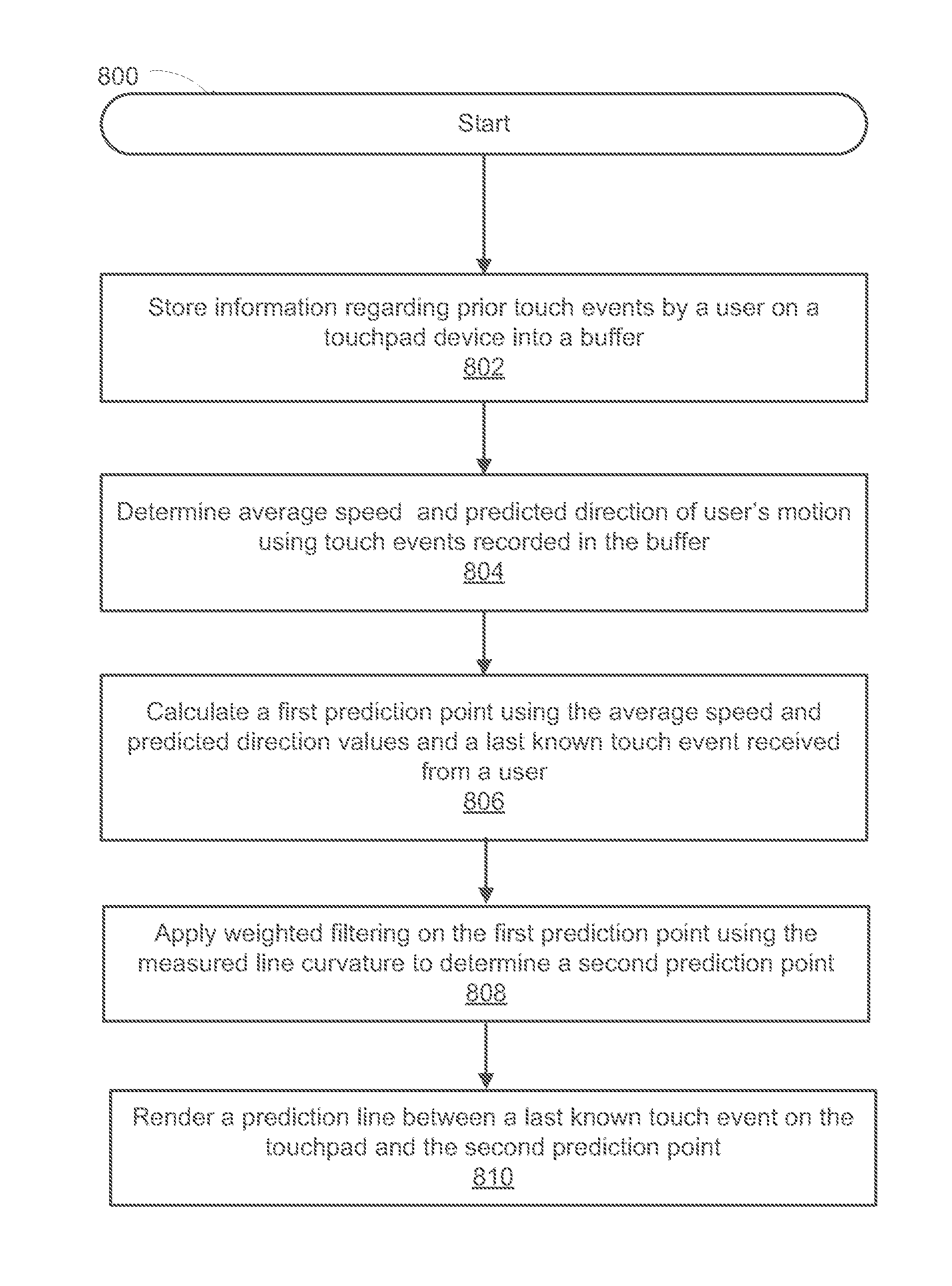
[0011]Accordingly, a need exists for systems and methods for reducing perceived pen-to-ink latency on touchpad devices by performing motion estimation and using the estimation to draw predictive lines on the touchpad screen, wherein the predictive lines reduce the user's perceived pen-to-ink latency. In one embodiment, the present invention computes the average speed of a stylus computes an estimated curvature of the line being drawn by the user and predicts a direction to perform motion estimation and then generates a predictive line segment.
[0012]Embodiments of the present invention can efficiently reduce perceived pen-to-ink latency without sacrificing the use of triple and double buffering by predicting pen movement to display predictive line segments and performing quick corrections once real touch events are processed. The prediction advantageously increases perceived responsiveness of the touch screen and makes touchpad devices feel more user interactive.
[0013]In one embodiment, a method for reducing display latency on a touchpad device is disclosed. The method comprises storing information regarding a plurality of prior touch events on a touch screen of the touchpad device into an event buffer. It further comprises determining an average speed and a predicted direction of motion regarding a user interaction with the touch screen using the plurality of prior touch events. Subsequently, it comprises calculating a prediction point using the average speed, the predicted direction, and a last known touch event on the touch screen. Finally, it comprises rendering a prediction line between the last known touch event on the touch screen and the prediction point.
[0015]In a different embodiment an apparatus to perform a method for reducing line display latency on touchpad devices is disclosed. The apparatus comprises a body, a bus, a touch screen display, wherein the touch screen display is operable to receive a user input through touch, a memory and a processor communicatively coupled to the memory and to the touch screen display via the bus, wherein the processor is configured to: (a) store information regarding a plurality of prior touch events on the touch screen display into an event buffer; (b) determine an average speed and a predicted direction of motion of a user interaction with the touch screen display using the plurality of prior touch events; (c) calculate a first prediction point using the average speed, the predicted direction, and a last known touch event on the touch screen display; (d) apply weighted filtering on the first prediction point using a measured line curvature to determine a second prediction point; and (e) render a prediction line between the last known touch event on the touch screen display and the second prediction point.

Problems solved by technology

Touchpad based devices typically suffer from a common problem.
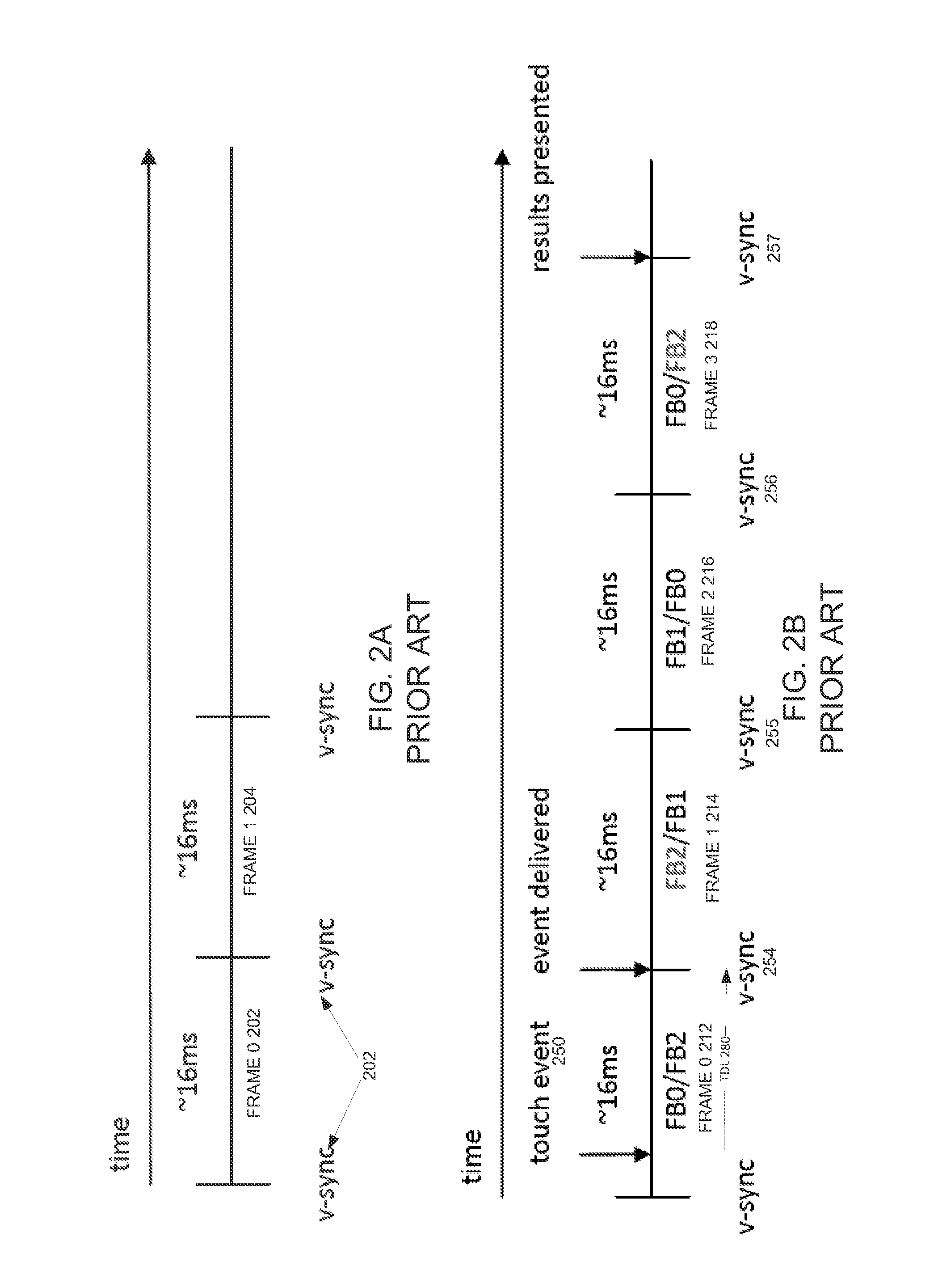
Assuming the application uses single buffering, this results in a minimum 16 ms delay before results of the user interaction are actually presented on display.
However, most operating systems on conventional devices, e.g. JellyBean, use triple buffering which make the delay even larger.
High latency results in lack of responsiveness and may lead to poor user experience, which can ultimately be a decisive factor in a consumer's decision whether to purchase a certain device.
Further, prior ways of trying to reduce latency related issues are unsatisfactory.
However, this is unsatisfactory because the advantages of triple buffering, e.g., a high frame rate are lost.

Method used


Image

  • Methods and apparatus for reducing perceived pen-to-ink latency on touchpad devices
  • Methods and apparatus for reducing perceived pen-to-ink latency on touchpad devices
  • Methods and apparatus for reducing perceived pen-to-ink latency on touchpad devices

Examples


Embodiment Construction

[0030]Reference will now be made in detail to the various embodiments of the present disclosure, examples of which are illustrated in the accompanying drawings. While described in conjunction with these embodiments, it will be understood that they are not intended to limit the disclosure to these embodiments. On the contrary, the disclosure is intended to cover alternatives, modifications and equivalents, which may be included within the spirit and scope of the disclosure as defined by the appended claims. Furthermore, in the following detailed description of the present disclosure, numerous specific details are set forth in order to provide a thorough understanding of the present disclosure. However, it will be understood that the present disclosure may be practiced without these specific details. In other instances, well-known methods, procedures, components, and circuits have not been described in detail so as not to unnecessarily obscure aspects of the present disclosure.

Notatio...


PUM


Abstract

A method for reducing line display latency on a touchpad device is disclosed. The method comprises storing information regarding a plurality of prior touch events on a touch screen of the touchpad device into an event buffer. It further comprises determining an average speed and a predicted direction of motion of a user interaction with the touch screen using the plurality of prior touch events. Next, it comprises calculating a first prediction point using the average speed, the predicted direction, and a last known touch event on the touch screen. Subsequently, it comprises applying weighted filtering on the first prediction point using a measured line curvature to determine a second prediction point. Finally, it comprises rendering a prediction line between the last known touch event on the touch screen and the second prediction point.

Description

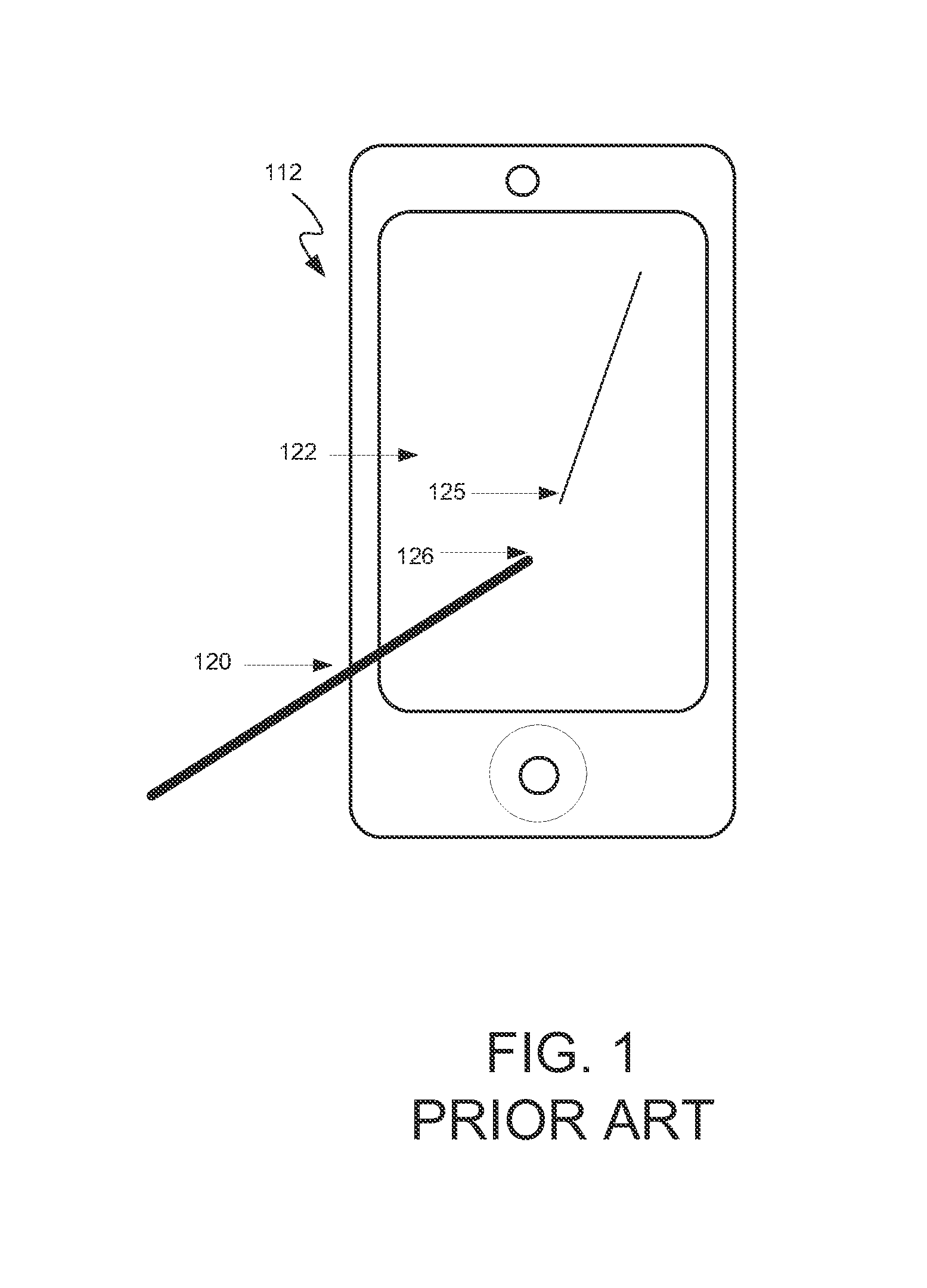
FIELD OF THE INVENTION[0001]Embodiments according to the present invention generally relate to touchpad devices and more specifically to methods for processing touch events on touch screens for touchpad devices.BACKGROUND OF THE INVENTION[0002]Touchpad based devices typically suffer from a common problem. When a stylus or similar device is used to draw a line or write some text on the touch screen of a touchpad device, there is a noticeable time lag between the actual pen movement and the “digital ink” appearing on screen. FIG. 1 is an exemplary illustration of “pen-to-ink” latency on a touchpad device. Stylus 120 is used to draw a line on touch screen 122 of device 112. As shown on touch screen 122, there is a time lag between the current position 126 of the stylus and the digital ink 125 being shown on the screen as it updates in response to the user's motion.[0003]This pen-to-ink latency is caused by a combination of factors, including hardware, software and operating system (OS)...

Claims


Application Information

Patent Timeline
Patent Type & Authority Patents(United States)
IPC IPC(8): G06F3/041G06F3/0488
CPCG06F3/04883G06F3/0416G06F3/03545G06F3/038G06F2203/04106G06T1/60
Inventor SKALJAK, BOJANTOORIANS, ARMANCHU, MICHAEL
Owner NVIDIA CORP
Learn More