Angular rate sensor

a technology of angular rate sensor and angular rate, which is applied in the direction of speed measurement using gyroscopic effects, instruments, surveying and navigation, etc., can solve the problems of low reliability, difficult unidirectional implementation, and non-vibratory (e.g., spinning) motion in microstructures

Active Publication Date: 2016-12-27
RAMOT AT TEL AVIV UNIV LTD
View PDF4 Cites 0 Cited by
  • Summary
  • Abstract
  • Description
  • Claims
  • Application Information

AI Technical Summary

Benefits of technology

[0010]It would therefore be desirable to have a vibratory gyroscope having increased actuating force, increased amplitude of in-plane oscillation, and optionally being less vulnerable to the instabilities.
[0011]The present invention provides a novel structure for vibratory gyroscopes, in which the amplitude of oscillation is not limited by a distance between the proof mass and the electrode. The present invention therefore enables the application of a large actuating force on the proof mass, and provides an increased space for the drive-mode oscillations to take place.
[0012]According to the present invention, a vibratory gyroscope is provided, in which a pair of spaced apart proof masses is present. Each mass is attached to an anchor via one or more flexible beams. Each of the beams is clamped at one of it ends whereas the other end is attached to the mass in such a manner that the slope between the deformed beam and the line corresponding to the initial shape of the beam remains zero at the attachment point (so-called “clamped-guided” beams). In other words, the deformed beam has a center of symmetry about an inflection (zero-curvature) point located at the midspan of the beam. An actuating electrostatic force varies in a periodic fashion over time and acts on each of the proof masses along the main axis of the beams. The electrostatic force may be produced by an electric potential applied to the pair of spaced apart proof masses, or to an electrode located between the proof masses. The periodic variation of the actuating force causes the proof masses to move in opposite directions with respect to each other. Since the masses always move in the opposite direction with identical amplitudes, the momenta of the masses has different sign. Therefore, the total momentum of two masses is zero and the center of gravity of two masses is fixed in space. This feature is beneficial because no momentum is transferred to the substrate through the anchors, resulting in smaller reaction forces acting on the anchors and consequently reduced radiation of elastic waves traveling away from the anchors and taking away part of the vibration energy (so-called acoustic losses of the device).
[0013]As described above, each of the proof masses is connected to one or more anchors by one or more beams. Preferably, each proof mass is connected to the anchor(s) by at least two beams. The periodic variation of the actuating force also causes the beams to fluctuate between a curved state and a straight state. When the beams are curved, the proof masses are pulled toward the respective anchors (movement along the main axis of the beams), while moving along an axis substantially perpendicular to the main axis of the beams. When the beams are straight, the proof masses are pulled toward each other (or toward the electrode between them), while moving along an axis substantially perpendicular to the main (longitudinal) axis of the beams. The movement along the main axis of the beams is considerably smaller than the movement along axes perpendicular to the main axis of the beams. Therefore the main oscillating motion of the proof masses occurs in a direction perpendicular to the main axis of the beams. This enables the proof masses to be located very close to the actuating electrodes or to each other, without limiting the oscillating motion along the axis perpendicular to the main axis of the beams. Moreover, since each proof mass is in its closest position to the electrode(s) when the beams are straight, no pull-in instability can occur due to very high tensile stiffness of the beams. Therefore, the device of the present invention is less prone to the pull-in instability.
[0014]The electrostatic actuating force acts on each of the proof masses along the main axis of the beams, resulting in a periodic tensile force applied to the beam's ends. This leads to the periodic variation of the effective stiffness of the structure, and consequently to parametric excitation of the device. Parametric excitation of a device is a harmonic excitation brought about by variation of the device's parameter(s) in time. The variation of the parameter(s) drives the system. When compared to non-parametric excitation, parametric excitation of the device brings about a sharper transition from low-amplitude non-resonance to high-amplitude resonance condition. Since the sense-mode oscillation is a growing function of the parametrically excitable drive-mode oscillation the amplitude of the sense mode oscillation of the device quickly rises in response to rotation (and therefore generation of the Coriolis force), increasing the sense mode velocity and oscillation amplitude, thereby raising the sensitivity of the gyroscope. Thus, the parametric excitation of the gyroscope of the present invention results in a quicker response and higher sensitivity of the gyroscope. In other words, higher amplitudes of the drive-mode motion produced by highly efficient parametric excitation result in higher amplitudes of the sense-mode motion and consequently in higher sensitivity of the device.
[0035]According to some embodiments of the present invention, the above device comprises a measuring unit for measuring at least one parameter of said oscillatory sense-mode movement, thereby enabling calculation of said rate of rotation.

Problems solved by technology

An implementation of unidirectional, non-vibratory (e.g., spinning) motion in microstructures is difficult due to low reliability of microfabricated parts performing relative motion unavoidably accompanied by contact, friction and possibly stiction.

Method used


Image

  • Angular rate sensor
  • Angular rate sensor
  • Angular rate sensor

Examples


Embodiment Construction

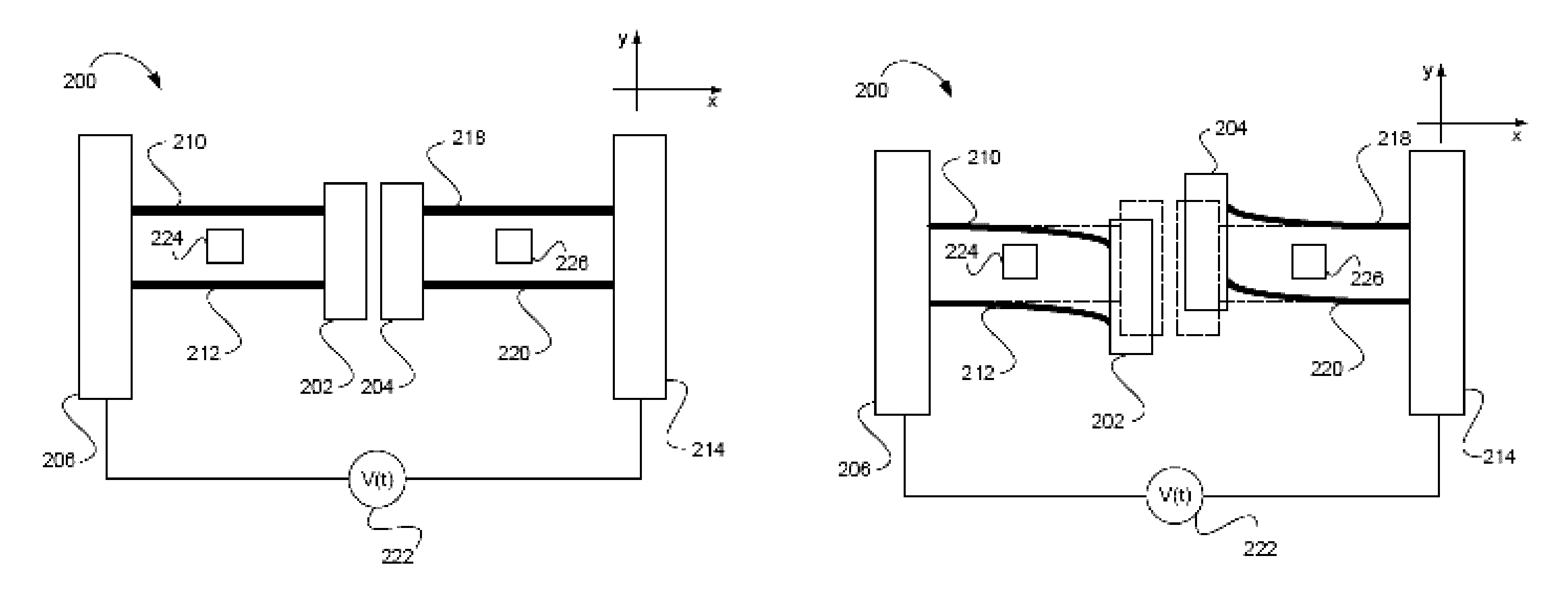
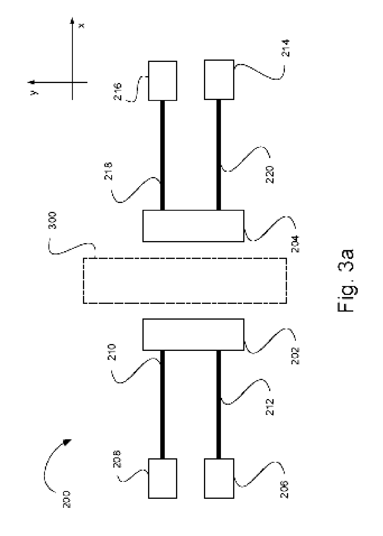
[0052]Referring now to the drawings, FIGS. 3a and 3b show schematically the gyroscope device 200 in accordance with two embodiments of the present invention. Generally, the gyroscope device 200 of the invention includes at least one pair of proof masses 202 and 204 which are coupled to anchors via an arrangement of suspended flexible beams and are associated with electrodes to be actuated / excited by application of electrostatic or magnetic force. The periodically induced deformation (tension) of the flexible beams causes parametric excitation, due to the periodic variation of the effective stiffness of the beams. The configuration is such that the beam is at its one end attached to the fixed anchor, and at the other “free” end is coupled to the proof mass. The electrostatic force may be applied by using direct voltage difference supply between two electrically conductive proof masses or via the use of electrodes. The latter may include a so-called “internal” or “central” electrode l...


PUM


Abstract

A rotation sensing device is presented. The device comprises: a proof mass arrangement comprising at least one pair of proof masses spaced-apart from one another along a first axis; a suspension assembly comprising flexible suspension beams having a main axis deformable between their substantially straight and curved states, the suspension assembly coupling the proof masses to an anchor assembly, while allowing a drive-mode oscillatory movement of the proof masses at least along a second axis substantially perpendicular to the main axis of the beams; and an actuation mechanism configured and operable to cause the drive-mode oscillatory movement of the proof masses in opposite directions along said second axis, thereby generating a sense-mode oscillatory movement of the proof masses during the rotation of the device about at least one rotation axis perpendicular to said second axis, said sense-mode movement being indicative of a rate of the rotation.

Description

TECHNOLOGICAL FIELD AND BACKGROUND[0001]This invention relates to the field of micro-electrical mechanical systems (MEMS), MEMS actuators, and more particularly to MEMS angular rate sensors.[0002]A gyroscope is a device for measuring an angle of rotation or angular velocity, based on the principles of conservation of angular momentum. Larger gyroscopes include one or more rotating portions, typically massive gimbaled disks or rings, the construction of which requires axes and bearings. An implementation of unidirectional, non-vibratory (e.g., spinning) motion in microstructures is difficult due to low reliability of microfabricated parts performing relative motion unavoidably accompanied by contact, friction and possibly stiction. Therefore, MEMS gyroscopes are generally realized as compliant vibratory gyroscopes.GENERAL DESCRIPTION[0003]There is a need in the art in a novel approach for fabricating MEMS based gyroscopes. This is associated with the following problems of the known t...

Claims


Application Information

Patent Timeline
Patent Type & Authority Patents(United States)
IPC IPC(8): G01C19/5642G01C19/574
CPCG01C19/5642G01C19/574
Inventor GERSON, YUVALKRYLOV, VIACHESLAVBAR-ON, YOTAM
Owner RAMOT AT TEL AVIV UNIV LTD
Why Eureka
Try Eureka