
Image forming apparatus that performs developer replenishment

a technology of developer replenishment and forming apparatus, applied in the field of image forming apparatus, can solve problems such as replenishment amount, and achieve the effect of accurate estimation

Active Publication Date: 2016-12-20
CANON KK
View PDF11 Cites 0 Cited by
  • Summary
  • Abstract
  • Description
  • Claims
  • Application Information

AI Technical Summary

Benefits of technology

The present invention provides an image forming apparatus that can accurately estimate the amount of developer replenishment needed and determine when to replace the developer replenishment unit. This is done by measuring the ratio of toner to developer and the amount of toner consumed from the developing unit, and controlling the output of the drive signal to the supply unit based on this information. By doing so, the apparatus can estimate the error in the amount of toner supplied and determine if replacement of the container is necessary, ensuring proper timing for the replacement.

Problems solved by technology

Further, according to the output of the drive signal, an error of the replenishment amount of toner supplied from the container to the developing unit is estimated based on the measured first information and the obtained second information, and it is determined based on the estimated error whether or not it is necessary to perform replacement of the container.

Method used


Image

  • Image forming apparatus that performs developer replenishment
  • Image forming apparatus that performs developer replenishment
  • Image forming apparatus that performs developer replenishment

Examples


first embodiment

[0079]Hereafter, a description will be given of a bottle near-end determination process for determining the replacement time of the toner bottle 60, performed by the image forming apparatus according to a

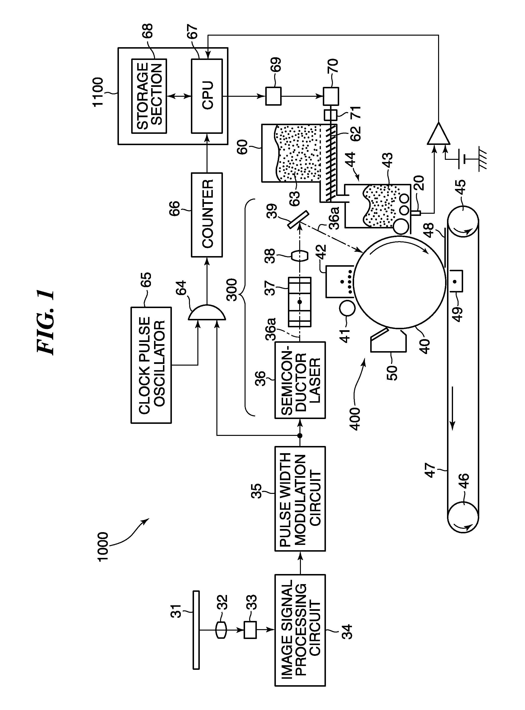
[0080]FIG. 6 is a block diagram of a toner replenishment controller of the image forming apparatus according to the first embodiment. Referring to FIG. 6, this toner replenishment controller, denoted by reference numeral 1200, differs from the toner replenishment controller 1100, shown in FIG. 4, in that a toner density-estimating section 1107, a toner replenishment amount error-estimating section 1108, and a forcible replenishment determination section 1110 are additionally provided. Further, the toner replenishment controller 1200 differs from the toner replenishment controller 1100, shown in FIG. 4, also in that first and second bottle near-end determination sections 1109 and 1111, a total bottle near-end determination section 1112, and a bottle replacement display section 1113 a...

second embodiment

[0149]The toner replenishment control process performed by the toner replenishment controller of the image forming apparatus is the same as the toner replenishment control process described with reference to FIG. 5, and hence description thereof is omitted.

[0150]Next, estimation of the toner replenishment amount error will be described with reference to FIG. 14. FIG. 14 is a flowchart of a toner replenishment amount error-estimating process. This process is started when the power of the image forming apparatus is turned on.

[0151]First, the CPU 67 invokes the immediately preceding values of delay operation variables from the storage section 68 (step S1301). Note that the delay operation variable includes state amount values stored in a step S1303, referred to hereinafter. It is to be understood that when the power of the image forming apparatus 1000 is turned on for the first time, a predetermined value of each delay operation variable is invoked from the storage section 68. The sta...


PUM


Abstract

An image forming apparatus includes a photosensitive member, an exposure unit, a developing unit that develops an electrostatic latent image using toner, a detection unit that detects an amount of the toner contained in the developing unit, and a calculation unit that calculates a difference value between the amount of detected toner detected and a target toner amount. In addition, an accumulation unit accumulates the calculated difference value, and a controller controls toner replenishing based on the calculated difference value and the accumulated value. A determination unit determines, based on an amount of the consumed toner and an amount of the contained toner, whether or not an error of an amount of replenished toner is larger than a threshold value, and determines, based on the number of times that the error is determined, whether or not replacement of the container is required.

Description

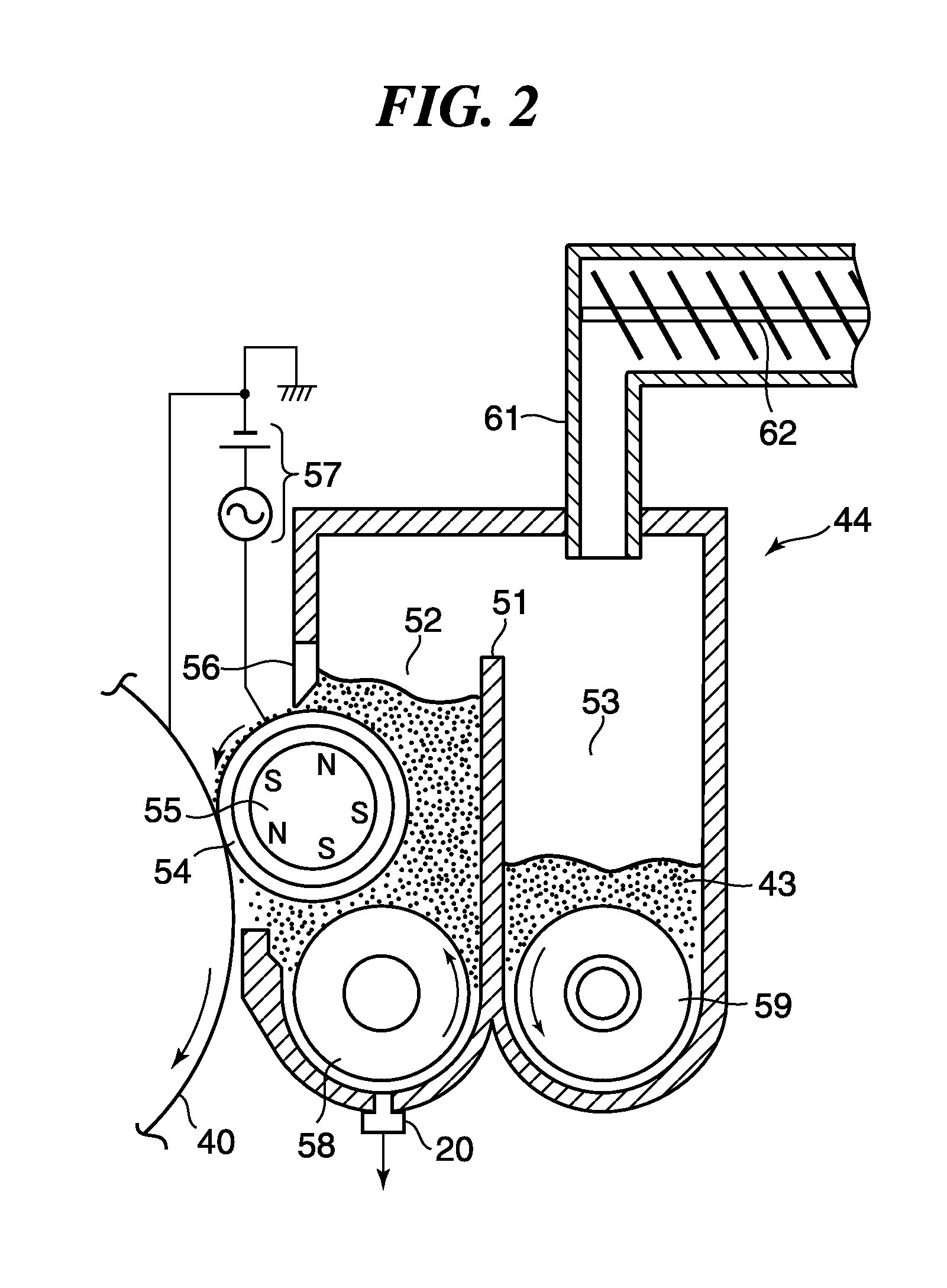
BACKGROUND OF THE INVENTION[0001]Field of the Invention[0002]The present invention relates to an image forming apparatus, and more particularly to an image forming apparatus that estimates an error of an amount of developer supplied to a developer containing section of a developing device, and determines a replacement time at which a developer bottle for supplying developer to the developing device is to be replaced.[0003]Description of the Related Art[0004]In an image forming apparatus, such as a copy machine and a laser beam printer, bottle near-end determination for determining a replacement time which is immediately before a toner (developer) bottle becomes empty is performed, and when it is determined that the toner bottle is in a near-end state, a message for prompting a user to replace the toner bottle is displayed.[0005]Conventionally, toner is supplied from a toner bottle to a developing device via a toner replenishment container, which is called a hopper. The hopper is pro...

Claims


Application Information

Patent Timeline
Patent Type & Authority Patents(United States)
IPC IPC(8): G03G15/00G03G15/08
CPCG03G15/556G03G15/0829G03G15/0832G03G15/0853G03G15/0865
Inventor OSHIMA, KANASHIRAKATA, JIROMIURA, SHUSUKE
Owner CANON KK
Learn More