Eureka AIR delivers breakthrough ideas for toughest innovation challenges, trusted by R&D personnel around the world.

Power supply line data transmission

a power supply line and data technology, applied in powerline communication applications, data switching networks, orthogonal multiplexes, etc., can solve problems such as data connection failure, severe consequences, and vehicle safety being compromised, and achieve simple and robust data transfer

Active Publication Date: 2016-11-29
MELEXIS TECH NV
View PDF8 Cites 5 Cited by
  • Summary
  • Abstract
  • Description
  • Claims
  • Application Information

AI Technical Summary

Benefits of technology

[0006]It is an object of embodiments of the present invention to provide simple and robust data transfer via a power supply line, e.g. via an automotive power supply line in a vehicle.
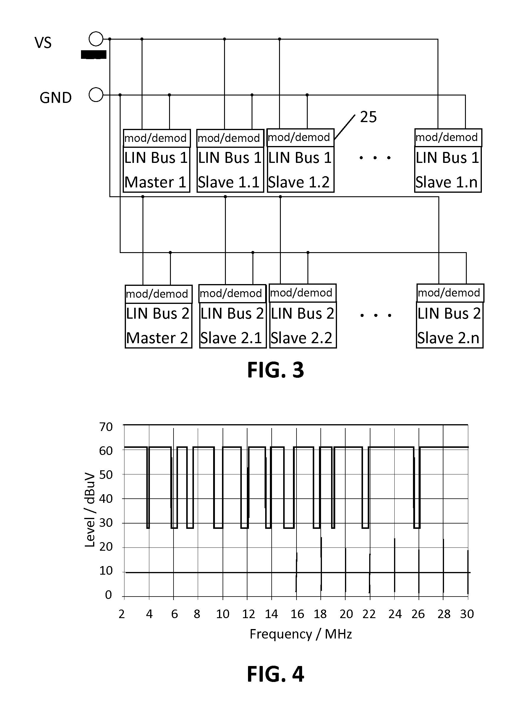
[0008]It is an advantage of embodiments of the present invention that robust data communication can be achieved over an automotive power line, e.g. over a low voltage direct current net used in vehicles, such as a 12 V DC net. For example, connection loss or data packet loss may be avoided in the dense and noisy environment of an automotive power supply network. It is an advantage of embodiments that reliable data communication can be achieved over an automotive power supply that may be subject to large fluctuations in its transfer function, e.g. by distributing the transmitted data over a relatively large bandwidth relative to the bandwidth of the communication signal itself.

Problems solved by technology

While this may be considered as a normal result of the spike in power use, or at least not as unexpected under these conditions, in a vehicle, e.g. a car, a data connection failure, even temporarily, could have severe consequences.
For example, vehicle safety could be compromised.
Furthermore, even if an automotive data communication error is not directly a risk to vehicle safety, from a user point of view it would be seen as very unpleasant, if, for example, a window lifter would not be operational in case the wipers are active.

Method used


Image

  • Power supply line data transmission
  • Power supply line data transmission
  • Power supply line data transmission

Examples


Embodiment Construction

[0044]The present invention will be described with respect to particular embodiments and with reference to certain drawings but the invention is not limited thereto but only by the claims. The drawings described are only schematic and are non-limiting. In the drawings, the size of some of the elements may be exaggerated and not drawn on scale for illustrative purposes. The dimensions and the relative dimensions do not correspond to actual reductions to practice of the invention.

[0045]Furthermore, the terms first, second and the like in the description and in the claims, are used for distinguishing between similar elements and not necessarily for describing a sequence, either temporally, spatially, in ranking or in any other manner. It is to be understood that the terms so used are interchangeable under appropriate circumstances and that the embodiments of the invention described herein are capable of operation in other sequences than described or illustrated herein.

[0046]Moreover, t...


PUM


Abstract

A transmitter and a receiver for transmitting and receiving data via a power supply line comprise a local signal port for respectively receiving and transmitting a serial bit stream and a power line connection port for respectively transmitting a radio frequency signal and receiving the radio frequency signal via the power supply line. The transmitter comprises a modulator unit adapted for encoding the serial bit stream into a baseband signal and generating the radio frequency signal by mixing the baseband signal with a carrier wave so as to redundantly convey the at least one baseband signal in at least four spectral sidebands of the carrier wave. The receiver comprises a demodulator unit adapted for detecting the at least four spectral sidebands of the carrier wave in the radio frequency signal, isolating a baseband signal from the at least four spectral sidebands and decoding the baseband signal into the serial bit stream.

Description

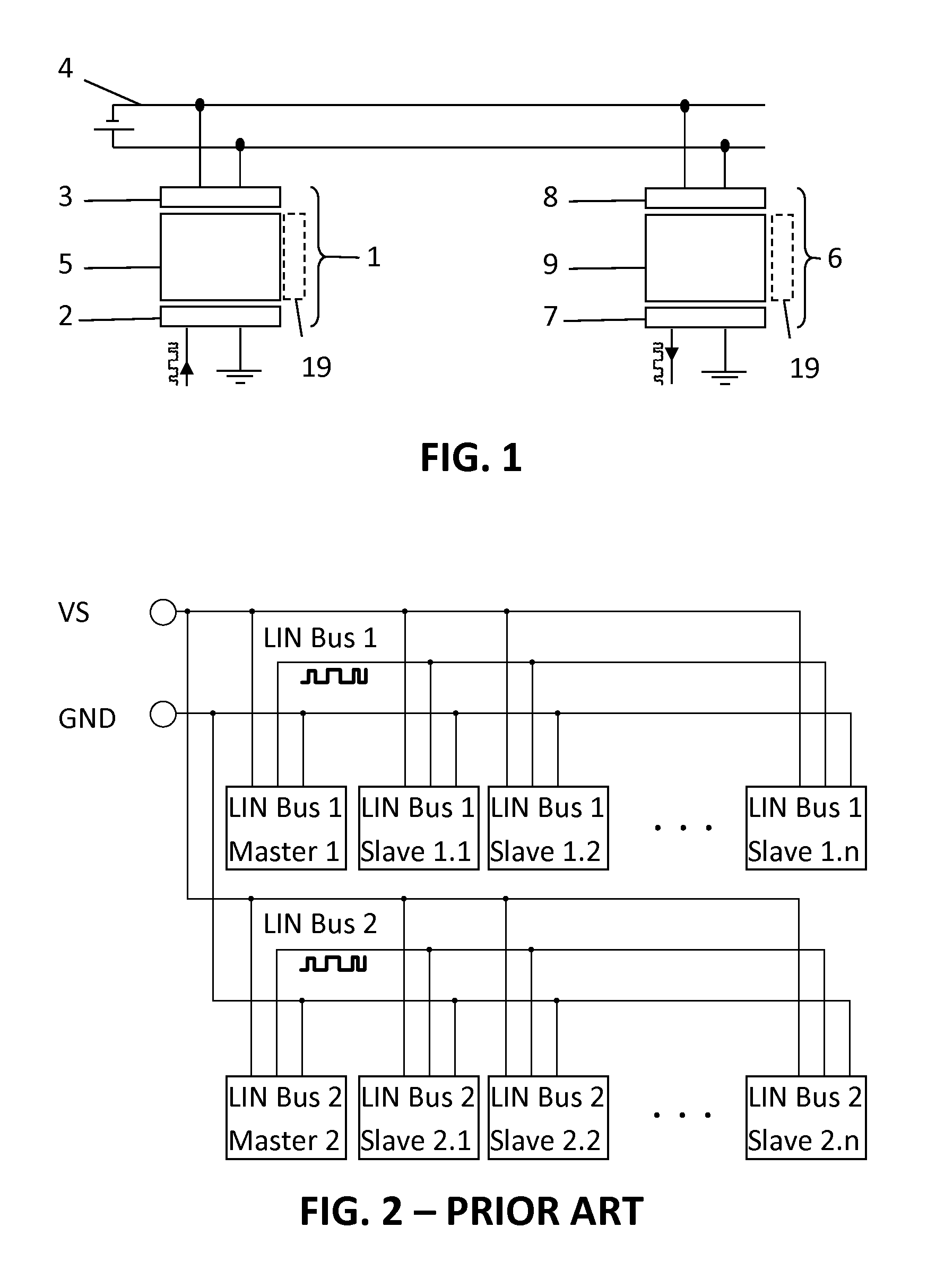
FIELD OF THE INVENTION[0001]The present invention relates to the field of data transmission networks. More specifically it relates to a transmitter, a receiver and a method for data communication over a power supply line, e.g. an automotive power supply line.BACKGROUND OF THE INVENTION[0002]The invention relates to data transfer, such as Local Interconnect Network (LIN) data communication, via a power supply line, e.g. an automotive power supply backbone. For example, LIN may be advantageously combined with a Power Line Communication (PLC) modem in order to avoid the need for additional signaling wires, e.g. a PLC approach may enable existing power cables to provide the physical layer for standard automotive communication protocols, or may act as a low-cost backup physical layer to critical communication lines.[0003]While data transfer over household power distribution lines is also known in the art, higher requirements on the robustness, e.g. in terms of Quality of Service, exist i...

Claims


Application Information

Patent Timeline
Patent Type & Authority Patents(United States)
IPC IPC(8): H04L1/22H04L12/40H04J11/00H04J13/00H04B3/54B60L11/18
CPCH04L1/22B60L11/1816B60L11/1838H04B3/54H04B3/542H04B3/548H04J11/00H04J13/00H04L12/40032H04B2203/547H04B2203/5416H04B2203/5445H04L2012/40215H04L2012/40234H04L2012/40273Y02T10/7005Y02T10/7072Y02T90/121Y02T90/128Y02T90/14Y02T90/16Y02T90/163Y02T10/70Y02T90/12
Inventor OTT, ANDREASFREITAG, THOMASBENDER, MICHAELFREY, MICHAEL
Owner MELEXIS TECH NV
Why Eureka
Eureka Blog
Learn More